


IS517 ECN4508
Page 11
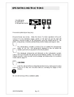
WARM AIR EXITS
AMBIENT A
IR IN
X
X
Y
Fig 2
CO
LD
AIR
EN
TER
S
CO
LD
AIR
EN
TE
RS
WA
RM
AIR
EX
ITS
WA
RM
AIR
EX
ITS
Fig 1
Fig 3
Ventilation requirements for drop in models
It is crucial for the operation of the
refrigeration system that a free flow of
air is maintained around condensing
unit.
The ideal method is to site the cabinet
within a counter where the back is
completely open as Fig 1.
These cabinets are designed to
eliminate the need for an unsightly vent
on the front of the counter providing
that the critical dimensions in Fig 2 are
observed and no there are no
obstructions in front of the air exhaust
that may be deflected into the path of
the incoming cold air.
The dimension X from the front grille of
the condenser to the inner face of the
counter front must not be less than
200mm.
If a shelf is required in the counter it
must allow adequate air flow beneath
the unit, dimension Y must be no less
than 200mm.
Fig 2 demonstrates how the air must
flow through the condenser to extract
the heat
.
To guarantee a flow of cool air
particularly where the back counter is
warm, then adequate vents can be
provided in the front of counter (see
Fig3) to ensure the refrigeration system
will only work satisfactorily.
The air inlet vents should be aligned
with condenser aperture and have total
free area greater than 900cm
2.
The air outlet also should be aligned
with power pack condenser air outlet
grill and have total free area greater
than 1000cm
2
.


