6. Software Control – Using Lightware Device Controller
MX2-8x8-HDMI20 series – User's Manual
23
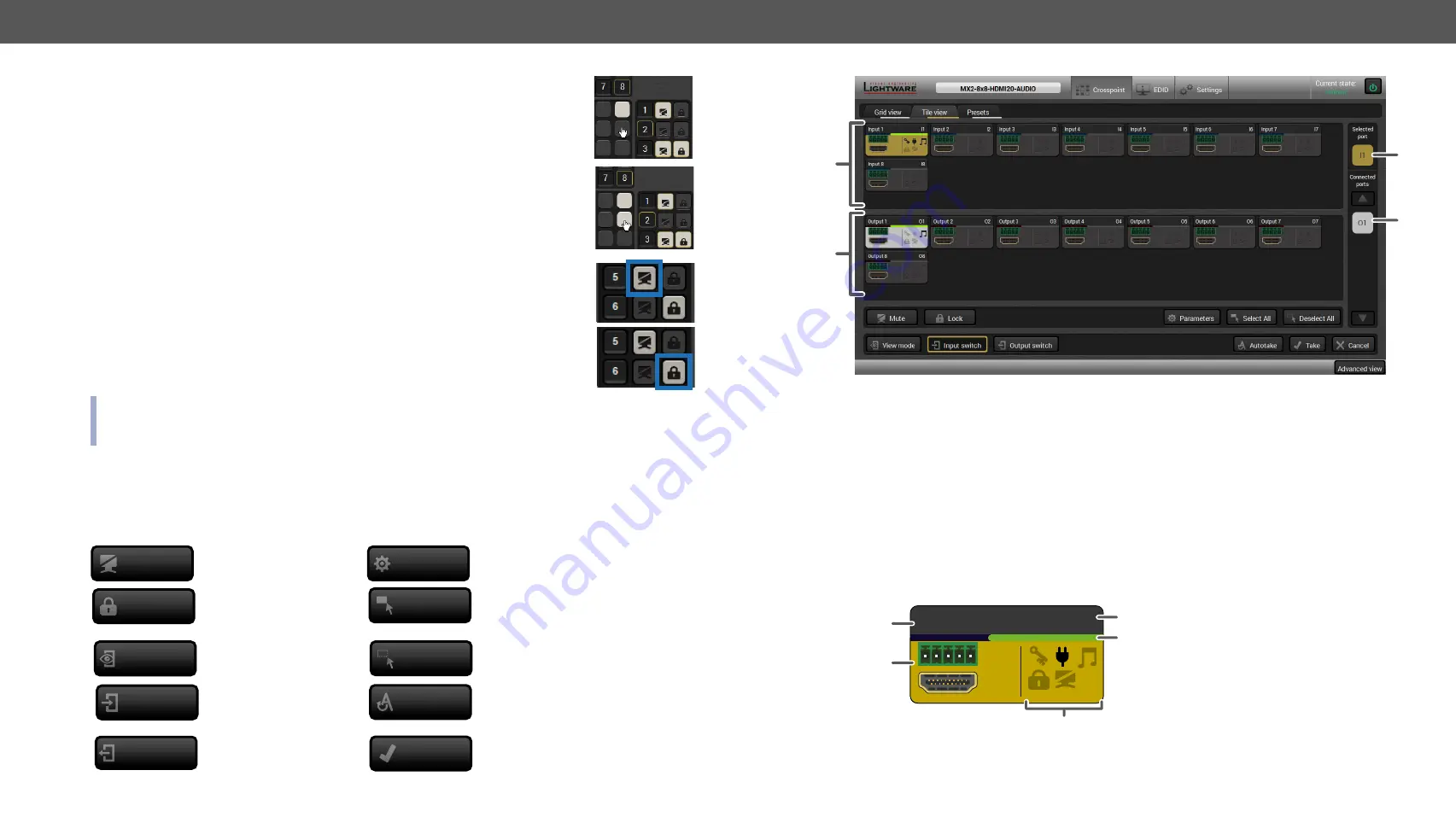
Crosspoint Operations
Switching
For making a connection click on the desired square. If there is no connection
between the desired input and output (the square is dark grey), the mouse pointer
becomes a hand (link pointer) before the clicking. If the output port is not locked,
the connection is made, the square becomes white and the cursor changes back
to a pointer.
For example, Input 8 is not connected to Output 2 as shown on the first picture. If
the connection is established the square becomes white. Input and output ports
can be disconnected when clicking on a white square.
Muting Outputs
Outputs can be easily muted by clicking on the button represented by a crossed
monitor beside the output. That means no signal is present on the given output. If
mute is active, the color of the button’s background changes to white.
Locking Outputs
Outputs can be locked to any input. After locking an output to an input, no switching is
permitted to this output unless it is unlocked again. If output lock is active, the color of
the button’s background changes to white.
INFO: Loading a preset does not change either the lock state or the switch state of a locked output. If an
output is locked to an input before preset loading it will also be locked to that input after preset loading,
so locked outputs ignore the preset.
6.3.2.
Tile View
The tiles represent input or output ports and additionally show the most important port and signal information.
Thus, the user can check the status of many ports at the same time.
Control Buttons
Mute or unmute selected
output port(s)
Open port properties window
Lock or unlock selected
output port(s)
Select all ports (only in output switch
mode)
View mode
Activate View mode
Deselect all ports (only in output
switch mode)
Activate Input switch mode
Toggle Autotake mode ON/OFF
Activate Output switch
mode
Execute crosspoint changes in Take
mode
Mute
Parameters
Lock
Select All
Deselect All
Input switch
Autotake
Output switch
Take
1
Input Ports
Each tile represents an input port.
2
Output Ports
Each tile represents an output port.
3
Selected Port
Last selected port is displayed with a yellow background on the port bar. Press the
button to open the port settings window.
4
Connected
Port(s)
The ports with white background are currently connected to the selected port.
Press the button to open the port settings window.
Port Tiles
The colors of the port tiles and the displayed icons represent different states and information about the
selected port:
Input1
I1
1
2
5
4
3
1
3
2
4
1
Port name
2
Background color:
grey
: not connected
yellow
: selected
white
: connected
3
Port number
4
Signal present indicator:
green
: present
grey
: not present
5
State indicators


