Lightware MX12x12DVI-Plus Скачать руководство пользователя страница 24


6. Software Control – Lightware Device Controller Software 

MX DVI-Plus Series – User's Manual 

24

6

Software Control – Lightware Device Controller 

Software

The matrix can be controlled by a computer through the USB, RS-232, and 

Ethernet port using Lightware Device Controller (LDC). The software can be 

installed on a Windows PC or macOS. The application can be downloaded from 

www.lightware.com

. The Windows and the Mac versions have the same look 

and functionality.

TIPS AND TRICKS: To get the best visibility of the screenshots in this chapter 

adjust the zoom setting of your PDF Reader software to 150% magnification.


Ý

Install and Upgrade


Ý

Running the LDC


Ý

Connecting to a Device (Device Discovery Window)


Ý

The Crosspoint Menu


Ý

Tile View


Ý

EDID Menu


Ý

Settings Menu


Ý

Terminal Window

6.1. 

Install and Upgrade

INFO: After the installation, the Windows and the Mac application 

has the same look and functionality. This type of the installer is 

equal with the Normal install in the case of Windows and results an 

updateable version with the same attributes.

Installation for Windows OS

Run the installer. If the User Account Control drops a pop-up message 

click Yes. During the installation you will be prompted to select the 

type of the installation: normal and the snapshot install:

Normal install

Snapshot install

Available for Windows


and macOS

Available for Windows

The installer can update 

only this instance

Cannot be updated

Only one updateable instance 

can exist for all users

More than one different version 

can be installed for all users

Comparison of the Installation Types

ATTENTION! 

Using the Normal install as the default option is highly 

recommended.

Installation for macOS

Mount the DMG file with double clicking on it and drag the LDC icon 

over the Applications icon to copy the program into the Applications 

folder. If you want to copy the LDC into another location just drag the 

icon over the desired folder.

The Upgrading of the LDC

Step 1. 

Run the application. 


The 

Device Discovery

 window appears automatically and the 

program checks the available updates on Lightware’s website 

and opens the update window if the LDC found updates. The 

current and the update version number can be seen at the top 

of the window and they are shown in this window even with 

the snapshot install. The 

Update

 window can be also opened by 

clicking the  

  (About) and the 

Update

 button.

Step 2. 

Set the desired update setting in the 

Options

 section. 


When the Check for updates automatically option is selected, 

the LDC tries to find a new version after startup The update can 

be postponed by setting a reminder; use the drop down list. 

The proxy settings can be set in a separate window.

Step 3. 

Click the 

Download update

 button to start. The updates can be 

checked manually by clicking the 

Check now

 button.

6.2. 

Running the LDC

The common way to start the software is double-click on the LDC 

icon. But the LDC can be run by command line parameters as follows:

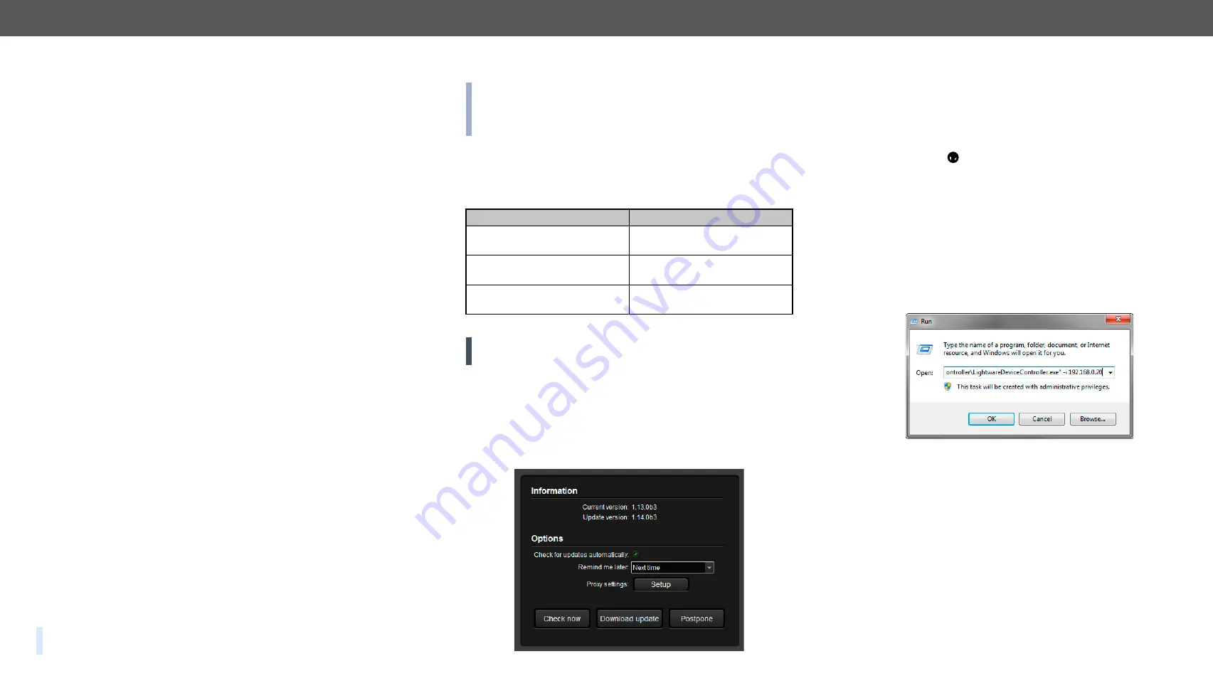
Connecting to a Device with Static IP Address

Format:


LightwareDeviceController -i <IP_address>:<port>

Example:


LightwareDeviceController -i 192.168.0.20:10001

The LDC is connected to a device with the indicated static IP address 

directly; the Device Discovery window is not displayed. When the port 

number is not set, the default port is used: 10001 (LW2 protocol). For 

LW3 devices use the 6107 port number.

Connecting to a Device via a Serial Port

Format:


LightwareDeviceController -c <COM_port>:<Baud>

Example:


LightwareDeviceController -c COM1:57600

The LDC is connected to a device with the indicated COM port directly; 

the Device Discovery window is not displayed. If no Baud rate is set 

the application will detect it automatically.

Содержание MX12x12DVI-Plus

Страница 1: ...MX9x9DVI Plus MX12x12DVI Plus MX16x16DVI Plus User s Manual Multimedia Matrix Switcher...

Страница 2: ...s free and never block or bypass the ventilators if any WARNING To prevent injury the apparatus is recommended to securely attach to the floor wall or mount in accordance with the installation instruc...

Страница 3: ...ormation Allpresentedfunctionsrefertotheindicatedproducts Thedescriptions have been made during testing these functions in accordance with the indicated Hardware Firmware Software environment Item Ver...

Страница 4: ...4 Presets 30 6 6 EDID Menu 31 6 6 1 EDID Operations 32 6 6 2 EDID Summary Window 32 6 6 3 Editing an EDID 33 6 6 4 Creating an EDID 33 6 7 Settings Menu 34 6 7 1 Configuration Tab 34 6 7 2 Device Inf...

Страница 5: ...ng the CPU 46 7 8 2 Restarting the EDID Controller 46 7 8 3 EDID Status Changed 46 7 8 4 Error Responses 46 7 9 Commands Quick Summary 47 8 FIRMWARE UPGRADE 49 8 1 Short Instructions 49 8 2 Detailed I...

Страница 6: ...can be used The switcher has an RS 232 and an RJ45 LAN port for remote control applications and a control panel for local control operation Front panel buttons are illuminated and reconfigurable with...

Страница 7: ...EU Hun gary RoH S E th er ne t 10 1 00 B id ir ec tio na l IR B id ir ec tio na l R S 2 32 TP S Lo ng Di st an ce Tr an sm itt er H D M I 3D 4K su pp or te d For bes t per form anc e use CAT 6 or CAT...

Страница 8: ...l by applying all mounting holes Choose properly sized screws for mounting Keep minimum two threads left after the nut screw threads 2 or more rack rail rack shelf mounting ear rack screw flat washer...

Страница 9: ...witching and function buttons are disabled 3 Destinations Buttons to select an output or to view the state of an output 4 Sources Buttons to select an input to select a preset number or to view the st...

Страница 10: ...DVI Outputs 29 pole DVI I connectors for outputs have only digital pins internally connected This way users can plug in any DVI connector but keep in mind that analog signals e g VGA or RGBHV are NOT...

Страница 11: ...usly or to reduce the potential differences which can appear during operation between the bodies of medical electrical devices and conductive parts of other objects 6 mm plug made of nickel plated bra...

Страница 12: ...e confirmed executed by the Take button as a final step The commands are only executed when the Take button is pressed If an operation is not confirmed by the Take button all preselected actions will...

Страница 13: ...lected This is indicated by a short flash of the Output lock when a locked destination is pressed Disconnecting or Muting in Take Mode Step 1 Press and release the selected source button The pressed s...

Страница 14: ...3 4 5 6 7 8 4 6 7 8 9 9 C CO ON NT TR RO OL L L LO OC CK K 3 5 LOAD PRESET 2 1 TAKE AUTO 2 L LO OC CK K O OU UT TP PU UT T SAVE PRESET 1 SOURCES DESTINATIONS 3 4 5 6 7 8 4 6 7 8 9 9 C CO ON NT TR RO...

Страница 15: ...he selected destinations are now locked SOURCES DESTINATIONS 3 4 5 6 7 8 4 6 7 8 9 9 C CO ON NT TR RO OL L L LO OC CK K 1 3 5 2 SAVE PRESET LOAD PRESET 2 TAKE AUTO L LO OC CK K O OU UT TP PU UT T 1 SO...

Страница 16: ...s outputs Input1 Input16 Emulated EDIDs inputs All EDIDs including factory preset user programmable memories EDID at other inputs and EDID at outputs can be switched and emulated at any of the inputs...

Страница 17: ...button to set DHCP enabled IP address Acquired with DHCP port number unchanged subnet mask Get from DHCP server gateway Get from DHCP server Step 5 A light sequence will occur to confirm the command T...

Страница 18: ...oom setting of your PDF Reader software to 150 magnification 5 1 Establishing the Connection To access the web page just run your preferred web browser and type the IP address of the matrix as an URL...

Страница 19: ...nd turns to red ATTENTION Loading a preset does not change either the lock state or the switch state of a locked output If an output was locked to an input before preset loading it will also be locked...

Страница 20: ...1 Select the Emulated EDID List in one of the window areas in the drop down list Step 2 Select the desired EDID list in the other window Step 3 Select the desired EDID from this list with a left mouse...

Страница 21: ...appear Click on this message to download the report file to the computer Step 3 Select the desired location and click on the Save button The default file name is Lightware_matrix_standard_report_devic...

Страница 22: ...uilt in website you have to type the IP address in your browser 5 5 2 Static IP Address Configuration The user can manually assign an IP address to the matrix and enter the related network settings As...

Страница 23: ...save the settings The new port will be active after the next connection 5 6 Terminal Menu This general purpose web terminal is intended mainly for test and debugs purposes All commands can be used he...

Страница 24: ...he LDC icon over the Applications icon to copy the program into the Applications folder If you want to copy the LDC into another location just drag the icon over the desired folder The Upgrading of th...

Страница 25: ...lity is the same as the Easy EDID Creator for the detailed information see the Creating an EDID section Demo mode This is a virtual MX FR17 matrix router with full functionality built into the LDC Fun...

Страница 26: ...buttons of the navigator 5 Input Boards The color of the line shows what kind of input boards are installed DVI 6 Connections Dark grey square means the port is not available Light grey square means...

Страница 27: ...ily muted by clicking on the button symbolized by a crossed monitor beside the output This means that no signal is present at this output If mute is active the color of the button s background changes...

Страница 28: ...utput port If window size does not allow to display all the ports pages can be turned by the left and right arrow buttons 3 Connected Port s Those ports are listed with white background on the port ba...

Страница 29: ...connected input port is shown Thus the output port connected to the input port can be changed Output ports can be un locked un muted only in Output switch mode 6 5 3 Crosspoint Operations Switching i...

Страница 30: ...and output ports Loading a Preset Step 1 Select the Presets tab from Crosspoint menu Step 2 Select the preset memory Preset1 Preset32 you want to load Step 3 Press the Load button the preset is loade...

Страница 31: ...current EDID was routed from The source reads the EDID from the Emulated EDID memory on the INPUT port Any EDID from any of the User Factory Dynamic EDID lists can be copied to the user memory EDID Em...

Страница 32: ...puter Step 1 Select the desired EDID from the Source panel the line will be highlighted with yellow Step 2 Press the Save button to open the dialog box and save the file to the computer Importing an E...

Страница 33: ...user All descriptors can be edited and saved in an EDID file or uploaded to the User memory For more details about EDID Editor please visit our website www lightware com and download EDID Editor user...

Страница 34: ...2 168 254 254 Subnet Mask 255 255 0 0 Default Gateway 0 0 0 0 Static IP Configuration In this case connected device has an IP address configuration set up by the user administrator Depending on modifi...

Страница 35: ...n the Log tab in the Settings menu Step 2 The Save as dialog box appears Select the place where you want to save the report file The default file name can be changed Step 3 LDC collects the needed inf...

Страница 36: ...programmer s reference The command text can be typed directly By default commands are automatically surrounded by framing brackets Every sent command and every received response gets an arrow or pref...

Страница 37: ...ed with multiple protocols The currently used protocol can be viewed or changed any time on the matrix front panel see the Control Protocols section or by protocol commands see the Querying the Curren...

Страница 38: ...outputs Legend 1 All Ox indexes show the corresponding output s connection state If value O5 equals 04 it means that output 5 is connected to input 4 All Ox indexes are two digit ASCII characters 01...

Страница 39: ...SE CrLf Format Example Command VM vm Response MUT M1 M2 M3 M4 M5 M6 M7 M8 M9 M10 M11 M12 M13 M14 M15 M16 CrLf MUT 1 0 1 1 0 0 0 0 0 0 0 0 0 0 0 0 CrLf Format Example Command out 03 Response 1MT out Cr...

Страница 40: ...NAME in iname 1 Response INAME in Input_name CrLf INAME 1 PC_1 CrLf 7 3 4 Renaming an Input Explanation Input 3 was named as Media_Player 7 3 5 Querying an Output Name Explanation Name for output 1 is...

Страница 41: ...TCP IP port 10001 mask subnet mask 255 255 0 0 gateway gateway address 0 0 0 0 Format Example Command IP_CONFIG ip_config Response Changing IP configuration CrLf Changing IP configuration CrLf DONE C...

Страница 42: ...CrLf ISD 10000000100100010000000000000000 CrLf Format Example Command OSD osd Response OSD OUTPUT_D CrLf OSD 010000001011000000000000 000000000 CrLf 7 6 Router Status Commands 7 6 1 Querying the Prod...

Страница 43: ...PLUS IB SCH_2 5 PCB_2 5 CrLf SL 7 Empty Slot CrLf SL 8 Empty Slot CrLf Format Example Command FC fc Response FIRMWARE_LIST CrLf CF MX CP FW 1 0 8 0x10 CrLf CF MX DVI EDID FW 3 2 3 0x50 CrLF Format Ex...

Страница 44: ..._S_C CrLf E_SW_OK CrLF delay E_S_C CrLf Format Example Command A loc a 48 Response E_SW_OK CrLf delay E_S_C CrLf E_SW_OK CrLF delay E_S_C CrLf 7 7 4 Querying the Emulated EDIDs Description Indexes sho...

Страница 45: ...111111111111111111111110000000 000000000000000000000000000000 000000001011111111111111110000 000000000000111131111111111100 00000000000000 CrLf Value Description 0 Invalid EDID 1 Valid EDID 3 Changed...

Страница 46: ...ription This response is sent after the commands which change the EDID EDID copy EDID switch or after a new EDID source e g a new display device is connected to the matrix Explanation Copy EDID from o...

Страница 47: ...tput_name Querying an Output Name 7 3 5 INAME id Renaming an Output 7 3 6 ONAME id Default Preset Names 7 3 7 PNAME id Default Input Names 7 3 8 INAME id Default Output Names 7 3 9 ONAME id Communicat...

Страница 48: ...ng the Emulated EDIDs 7 7 4 VEDID Saving an EDID Learning 7 7 5 out loc Viewing the EDID Header 7 7 6 WV Querying the EDID Validity Table 7 7 7 WH loc Downloading the Content of an EDID 7 7 8 WE loc U...

Страница 49: ...rmware files Step 2 Install the Application and Prepare the Firmware Files Run the Bootloader installer installing the application to the default destination is recommended If you got the firmware fil...

Страница 50: ...esired device is not discovered for some reason but you know its IP address you can add it manually Press the Add IP button and fill the text boxes Double click on the IP address then click Yes to est...

Страница 51: ...n on Now the matrix is ready to be used with the new firmware 8 3 Error Messages Upgrade failed If the connection is unreliable and the Bootloader cannot communicate with the Lightware device then the...

Страница 52: ...e monitor is replaced with another display device as long as it has a valid EDID EDID is independently programmable for all inputs without affecting each other All inputs have their own EDID circuit I...

Страница 53: ...g temperature 0 to 55 C 32 F to 122 F Operating humidity 10 to 90 non condensing Power Power source 100 240V AC 50 60Hz Power consumption of MX9x9DVI Plus typ max 27W 36 W Power consumption of MX12x12...

Страница 54: ...i 50 0 Hz yes F39 1920 x 1080i 60 5 Hz yes F40 1920 x 1080 24 0 Hz yes F41 1920 x 1080 24 99 Hz yes F42 1920 x 1080 30 0 Hz yes F43 1920 x 1080 50 0 Hz yes F44 1920 x 1080 49 99 Hz yes F45 1920 x 1080...

Страница 55: ...AD PRESET TAKE AUTO 1 2 3 4 5 6 7 8 9 10 11 12 13 14 15 16 RS 232 I N P U T S 1 2 3 4 5 6 7 8 9 10 11 12 13 14 15 16 O U T P U T S 3 3V 5V RESET CPU LIVE LAN 100 240V 2 1 0 9A 50 60Hz FUSE F 3 15A 250...

Страница 56: ...orehand 2 2 Used in any application other than that for which it was intended 2 3 Subjected to any mechanical or electrical abuse or accidental damage 2 4 Any costs incurred for repair replacement of...

Отзывы: