background image

SCREEN

1

3

2

DMX 512

3 PIN

SIGNAL

SIGNAL


SIGNAL

SCREEN

DMX512

5 PIN

1

2

3

4

5

SIGNAL

PIN3

PIN2

9

DMX


IN


IN


OUT


OUT


IN


OUT

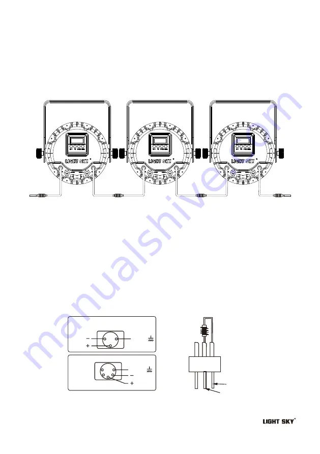
2.Signal connection

Please use the round 3/5-pin XLR plugs &sockets offered by menu facture to connect the 
first projector's output to the second projector' input and connect the second projector's 
output to the third device's input. And in the same way for the rest, eventually connect the
 last device's output, all the devices are together as the following figure.
The devices' control signal output or input by using the 3/5-pin XLR pug and socket. 
If need to long then the communication cable, please make sure the both side of 
3/5-pin plug is one to one. (one to one, two to two, three to three). Otherwise, the 
communication cable will be interrupted.

Connecting to the control signal line (DMX) - Fig. 5

 Please use the round 3 or 5-pin XLR plugs &sockets  offered by menu facture  to connect the  first 

    projector's output to the second projector' input and connect the second projector's output  to the 
    third projector's input. And in the same way for the rest,eventually connect  the last  projector's 
    output,all the projectors are together.

The projectors's control signal  output or input by using the 3 or 5-pin XLR pug and socket.If need to 

    lengthen the communication cable,please make sure the both side of  3 or 5-pin plug is one to one .
   (one to one,two to two,three to three).Otherwise,the communication cable will be interrupted.The 
   communicate cable is  2-cord screened  cable 75

Ω

 resistance with each core is  at least a 0.5mm 

   diameter.(

Caution:

All the inside leading wire of  3 or 5-pin XLR plug couldn't  touch each other or 

   plinth).

Recommend to use the DMX signal terminator for the installation to avoid the electronic noise dama

   -ge the digital control signal.Simply speaking,DMX terminator is an XLR connector with a 120

Ω

 1/2W 

  resistor connected across pin 2 and 3.Which is then plugged into the output socket on the last projec
  -tor in the chain.Refer to the connection. 

Содержание PL6103

Страница 1: ...PL6103 E mail n Address No 43 Yunfeng Road Xiuquan Street Huadu District Guangzhou China...

Страница 2: ...all liability for damage to the fitting or to other property or persons deriving from installation use and maintenance that have not been carried out in conformity with this user manual which must al...

Страница 3: ...able should be connected with the ground cable of the power supply system as well The ground mark of the light metal cover should be connecting with the installation bricked steadily 4 Don t use the p...

Страница 4: ...ontrol Mode DMX512 Stand alone mode Mater Slave mode Channel Standard 12CH 16Bit mode 12CH RGB mode 5CH HSI mode 5CH Control panel LED display screen keypad Structure Aluminum material honeycomb desig...

Страница 5: ...Control panel 4 POWER IN POWER OUT DMX OUT DMX IN Keypad Display screen...

Страница 6: ...Attachment and Body size 5 power cord Body Size Fig 2 2 1 347 210 291 335 258 Each of the six stage lights delivers a power cord and a signal line...

Страница 7: ...1180 430 250 136 8 14 25 68 62 115 195 530 R G B RGBW 270 100 59 31 W 57 104 191 510 0 55 0 9 1 2 7 5 3 Distance m 0 10 1 75 9 3 6 5 4 8 2 8 10 Diameter m 50 Diameter m 1m 2m 3m 4m 5m 5m 4m 3m 2m 1m...

Страница 8: ...ine knowledge of the installation material being used and periodic safety inspection of all installation material and the fixture If you lack these qualifications do not attempt the installation yours...

Страница 9: ...olor coding and power connections Power supply and signal connection 1 Power supply Use the professional plug to connect the projector and main power supply Please pay attention to the voltage frequen...

Страница 10: ...to connect the first projector s output to the second projector input and connect the second projector s output to the third projector s input And in the same way for the rest eventually connect the...

Страница 11: ...e OFF DIM 1 DIM 2 DIM 3 DIM 4 OFF CUR 1 CUR 2 CUR 3 CUR 4 Dimmer speed off DMX F HOLD BLAC R G B W SET 2 Menu operation Standard channel mode Level 2 menu Level 3 menu Level 4 menu Dimmer speed 1 Dimm...

Страница 12: ...e No signal Built in program 1 No signal Built in program 2 No signal Built in program 3 No signal Built in program 4 Slave machine Speed of built in program without DMX signal Master machine Focus po...

Страница 13: ...0 R 000 G 000 W 000 M 000 Z 000 B 000 SERV Factory settings Factory default Level 1 menu Level 2 menu default Keep password 1111 Enter Dimmer Strobe Red Green Blue White Macro Zoom Note Level 3 menu L...

Страница 14: ...34 35 46 47 70 71 98 99 100 No Function Fast closing Slow opening Sloe Fast Slow closing Fast opening Sloe Fast Slow closing Slow opening Sloe Fast Random strbe Sloe Fast Synchronous strbe Sloe Fast N...

Страница 15: ...immer Speed 1 Fastest 0 9 NO Function Linear Dimmer Dimmer Speed 2 Dimmer Speed 3 Dimmer Speed 4 Slowest 10 29 3 6 11 3 30 69 11 4 27 70 129 130 189 190 255 27 1 50 5 50 6 74 1 74 2 100 129 255 0 50 5...

Страница 16: ...t closing Slow opening Sloe Fast Slow closing Fast opening Sloe Fast Slow closing Slow opening Sloe Fast Random strbe Sloe Fast Synchronous strbe Sloe Fast NO Function 3 4 5 6 7 8 9 10 0 255 0 100 0 2...

Страница 17: ...98 99 100 4 0 255 0 100 0 255 0 100 0 255 0 100 0 255 0 100 Saturation Hue Intensity 5 1 2 3 HSI channel mode 5CH RGB channel mode 5CH FUNCTION DMX VALUE CHANNEL FUNCTION DMX VALUE CHANNEL No Function...

Страница 18: ...1AS D1 PL4803 XS VER 1 1 2008 09 L N Dreiver board LED board Display board Switching power supply Power in in put LED OUTPUT W R2 G2 B2 W R1 G1 B1 TEM R2 G2 B2 B1 G1 R1 DC48V INPUT V1 1 20170511 6103Z...

Страница 19: ...on option are correct 2 Please check whether the communicate control cable is on good connection or the cable is too long or interrupt 3 Please check the control system is not valid check the signal a...

Страница 20: ...is best not over 48 hours or it would generate lamp protection procedure 3 Please disconnect the power supply when begin to maintenance take down the light Please let the parts cool down 10 minute at...

Отзывы: