background image


10 


ROWER-405


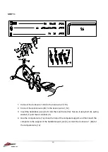
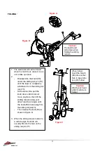
STEP 5: 


1.  Connect the trunk wire 1 (9b) to the trunk wire 2 (11b) 


2.  Connect the tension wire (2b) to the tension wire 2 (12)


3.  Insert the handlebar post join (5) into the main frame (52). Secure it using bolt (8), spring 

washer (7) and the arc washer (6)


4.  Use the computer wire (1a) cross the hole of the computer support, and then insert the 

computer to the support of the handlebar post join (5), connect the trunk wire 1 (9a) tot 

the computer wire (1a)


Содержание ROWER-405

Страница 1: ...roduct may vary slightly from the item pictured due to model upgrades Read all instructions carefully before using this product Retain this owner s manual for future reference ROWER 405 OWNER S MANUAL...

Страница 2: ...2 ROWER 405 TABLE OF CONTENTS 1 IMPORTANT SAFETY INSTRUCTIONS 3 2 ASSEMBLY INSTRUCTIONS 5 3 DISPLAY MANUAL 5 4 EXERCISE GUIDE 14 5 EXPLODED DIAGRAM 18 6 PARTS LIST 19 7 WARRANTY 21...

Страница 3: ...or s advice is essential if you are taking medication that affects your heart rate blood pressure or cholesterol level c Be aware of your body s signals Incorrect or excessive exercise can damage your...

Страница 4: ...estrict or prevent movement h This equipment is designed for indoor and family use only The Max user weight is 120KG i Care must be taken when lifting or moving the equipment so as not to injure your...

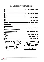
Страница 5: ...5 ROWER 405 2 ASSEMBLY INSTRUCTIONS...

Страница 6: ...6 ROWER 405 STEP 1 1 Attach the front stabilizer 54 onto the main frame 52 using the square neck bolt 55 arc washer 6 spring washer 7 and cap nut 7...

Страница 7: ...sensor 84 onto the sliding rail join 73 to the trunk wire 2 11b of the main frame 52 3 Insert the sliding rail join 73 onto the main frame 52 then lock it by the bolt 74 washer 71 and nylon nut 70 cap...

Страница 8: ...52 and then assemble the footplate sack 48 onto each side Then secure it with the washer 32 spring washer 7 and the nut 46 2 Insert the footplate axis 40 into the main frame 52 assemble the footplate...

Страница 9: ...9 ROWER 405 STEP 4 1 Lock the pedal 23L and 23R on each pedal rod post 18L and 18R using bolt 22 washer 20 and nylon nut 21...

Страница 10: ...wire 2 12 3 Insert the handlebar post join 5 into the main frame 52 Secure it using bolt 8 spring washer 7 and the arc washer 6 4 Use the computer wire 1a cross the hole of the computer support and th...

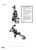
Страница 11: ...e same time pull the knob down until it cannot move anymore then lift the sliding rail join using your other hand to an angle until the knob 50 brake away from the sliding rail join 73 Then release th...

Страница 12: ...till it cannot be moved At the same time lower the sliding rail join 73 to an angle until you can release the knob 50 As shown in Figure D 3 When the sliding rail join 70 rotates on the floor the kno...

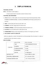
Страница 13: ...d 4 STROKES OVERALL Count the total rowing strokes from start to end 5 KJLOULE Count the total kjoule from rowing start to end 6 STROKES MIN Display current rowing strokes per minute or the frequency...

Страница 14: ...tensity of your maximum heart rate zone Start at the lower intensity and build up to higher intensity as you become more aerobically fit If you feel dizzy or lightheaded you should slow down or stop e...

Страница 15: ...is 140 beats per minute A six second count is used because your heart rate will drop rapidly when you stop exercising Adjust the intensity of your exercise until your heart rate is at the proper level...

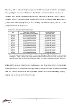
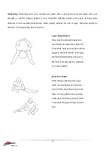
Страница 16: ...Do not bounce Lower Body Stretch Place feet shoulder width apart and lean forward Maintain this position for 30 seconds using the body as a natural weight to stretch the backs of the legs DO NOT BOUN...

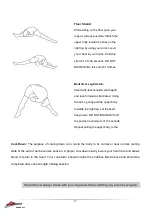
Страница 17: ...aining session Floor Stretch While sitting on the floor open your legs as wide as possible Stretch the upper body toward the knee on the right leg by using your arms to pull your chest to your thighs...

Страница 18: ...18 ROWER 405 5 EXPLODED DIAGRAM...

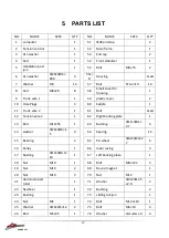
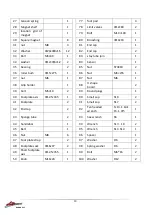
Страница 19: ...Plugs 3 60 Saddle 1 11 Trunk wire 2 1 61 Bolt 2sets 12 Tension wire 2 1 62 Right backing plate 1 13 Bolt M10 55 1 63 Bushing 11 8 1 2 7 6 14 washer 20 10 1 5 4 64 bearing 12 15 Bearing 2 65 PU wheel 4...

Страница 20: ...15 27 5 1 86 Nut M6 L55 1 37 nut M6 1 87 Nut M6 1 38 Grip holder 1 88 U shape board 2 39 bolt M5 10 2 89 Round plugs 1 40 Footplate axis 12 5 435 1 90 Small cap S19 2 41 Footplate 2 91 Small cap S17 2...

Страница 21: ...ent or refund for a major failure and compensation for any other reasonably foreseeable loss or damage You are entitled to have the goods repaired or replaced if the goods fail to be of acceptable qua...

Отзывы: