5
RC-81
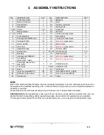
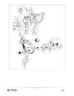
3. ASSEMBLY INSTRUCTIONS
NO.
DESCRIPTION
Q’TY
NO.
DESCRIPTION
Q’TY
1
Front main frame
1
24
Backrest
1
2
Rear main frame
1
25
Seat
1
3
Seat bracket
1
26
Tension controller
1
4
Handlebar
1
27
Spring knob
1
5 L/R
Crank
1 pr
28
Computer
1
6
Rear stabilizer
1
29
End cap
4
7 L/ R Pedal
1 pr
30
Cross pan head screw
4
8
Front stabilizer
1
31
Flat washer
1
9
Carriage bolt M8*55*L20
4
32
Cross pan head screw
1
10
Flat washer D8
30
33
Extension
pulse wire 1
2
11
Acorn nut M8
6
34
Sensor wire
1
12
Plum bolt
1
35
Extension
pulse wire 2
2
13
Adjustable tube
1
36
Tension cable
1
14
Square cap
2
37 L/R
Front end cap
1 pr
15
Bushing
2
38
Rear end cap
2
16
Carriage bolt M8XL45
2
39
Extension
pulse wire 3
2
17
Arc washer
φ8.2×φ16*1.5 R20
2
40
Extension sensor wire
1
18
Cross pan head screw
ST4.2X18
5
41
Handlebar post
1
19
Foam grip
2
42L/R
Handlebar L/R
1 pr
20
Knob
1
43
Foam grip
2
21
Inner hex screwM8×15
26
44
Flat washer D6 X1.2 Xφ16
4
22
Extension pulse wire 4
2
45
Inner hex screw M6×40
4
23
Square cap
2
46
Cover
1
NOTE:
Most of the listed assembly hardware has been packaged separately, but some hardware items have been
preinstalled in the identified assembly parts. In these instances, simply remove and reinstall the hardware as
assembly is required.
Please reference the individual assembly steps and make note of all preinstalled hardware.
PREPARATION: Before assembling, make sure that you will have enough space around the item; Use the
present tooling for assembling; before assembling please check whether all needed parts are available.
It is strongly recommended this machine to be assembled by two or more people to avoid possible injury.
Содержание RC-81
Страница 6: ...6 RC 81...


