

8
ASSEMBL
Y
INSTRUCTIONS
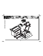
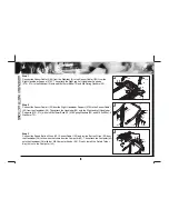
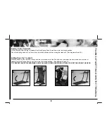
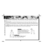
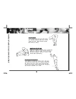
Step 1
Connect the Sensor Cable III (24) from the Stabilizer (2) to the Sensor Cable II (23) from the
Right Handlebar Support (37R). Then attach the Right and Left Handlebar Supports
(37R, 37L) to the Stabilizer (2) with six M8x16mm Bolts (70) and M8 Spring Washers (52).
Step 2
Connect the Sensor Cable II (23) from the Right Handlebar Support (37R) to the Sensor Cable I
(22) from the Handlebar (38). Then attach the Handlebar (38) onto the Right and Left Handlebar
Supports (37R, 37L) with six M8x16mm Bolts (70), M8 Spring Washers (52), and Ø 8.5xØ 16x1.5
Washers (72).
Step 3
Connect the Speed Button Wires (40), Sensor Cable I (22), and Incline Button Wires (29) from
the Handlebar (38) to the wires that come from the Computer (43). Then attach the Computer (43)
onto the Handlebar (38) with four M5 Computer Knobs (25). Finally, install the Safety Tether
Key (44) onto the Computer (43).
37R
70
52
70 52
23
24
52
70
37L
38
37R
37L
38
70
52
72
22
23
70
52
72
70
52
72
72
52
70
22
29
25
25
43
44
40
2
1
2
3


