background image

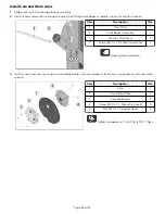
7.

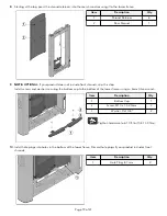
Install screw and washer securing the thigh pad assembly to the pivot boom assembly using a 7mm Allen wrench.

Item

Description

Qty.

1

Thigh Pad Assembly

1

2

Pivot Boom Assembly

1

3

Screw, M10 x 1.5, 30mm Low Head

1

4

Washer, Flat 30mm

1

5

Bearing Housing Cap

1

 Tighten hardware to 14-16 ft-lb (19-21.7 Nm).

8.

Install bearing housing cap to the pivot boom assembly using a rubber mallet.

Cable Routing

1.

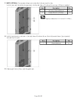
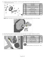
Route cable out through the hole on the side of the tower frame. Route cable through the pulley support assembly.

2.

Slide the carriage bolt to the end of the slot in the pulley support assembly using a 17mm wrench.

Item

Description

Qty.

1

Carriage Bolt, M10 x 1.5, 50mm

1

 Tighten hardware to 20-25 ft-lb (27.1-33.9 Nm).

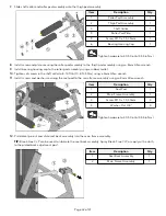
3.

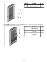
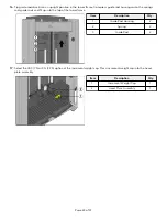
Slide pulley support assembly onto the pivot shaft and align with holes in the tower frame.

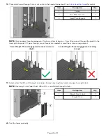
NOTE: Press the pivot shaft into the pulley arm assembly so approximately ¼" is exposed to get the pulley support
assembly to align with the tower frame.

Page 26 of 41

Содержание Axiom OP-SLCE

Страница 1: ...Axiom Series Seated Leg Curl Extension OP SLCE Assembly Instructions 1015206 0001 REV AA ...

Страница 2: ......

Страница 3: ...inato ku Tokyo 107 0062 Japan Telephone 81 0120 114 482 Fax 81 03 5770 5059 Service Email service lfj lifefitness com Sales Marketing Email sales lifefitnessjapan com Latin America and Caribbean Life Fitness LLC Columbia Centre III 9525 Bryn Mawr Avenue Rosemont IL 60018 U S A Telephone 847 288 3300 Service Email customersupport lifefitness com Sales Marketing Email commercialsales lifefitness com...

Страница 4: ...o osagarria eskuragarri dago goiko estekaren bidez Допълнителна информация можете да намерите онлайн като използвате връзката по горе Mitjançant l enllaç anterior podreu accedir a informació addicional en línia 使用上面的連結線上提供額外資訊 Dodatne informacije možete pronaći na internetu sljedeći vezu iznad ከላይ የተቀመጠውን አገናኝ ሊንክ በመጠቀም መረጃዎች ኦንላይን ያገኛሉ Lisätietoja on saatavissa verkosta käyttämällä yllä olevaa li...

Страница 5: ...tatic Anchor Procedure 39 Foot Dimensions 41 Life Fitness is a registered trademark Gym Wipes is a registered trademark of the 2XL Corporation PureGreen 24 is a trademark of Pure Green Copyright 2021 Life Fitness LLC All Rights Reserved Life Fitness Hammer Strength Cybex ICG and SCIFIT are registered trademarks of Life Fitness LLC and its affiliated companies and subsidiaries Brunswick and related...

Страница 6: ...ommended that the equipment be located in an access controlled area Control is the responsibility of the facility owner Installation Life Fitness Family of Brands recommends that all equipment be secured to a solid level surface to stabilize it and eliminate rocking or tipping over This must be performed by a licensed contractor See Bolt to Floor Guide for installation procedure Proper Usage Do no...

Страница 7: ...ins Partial insertion can cause weights to fall unexpectedly Never pin the weight stack in an elevated position Never remove selector pin if any weights are suspended Never attempt to release jammed weights or parts Never use dumbbells or other means to incrementally increase the weight resistance Use only those means provided by seller Warnings and Cautions Warning labels indicate a potentially h...

Страница 8: ...Product Labels General Warning Serial Number Pinch Hazard Page 6 of 41 ...

Страница 9: ...Label Locations Item Description Qty 1 General Warning 1 2 Serial Number 2 3 Pinch Hazard 5 Page 7 of 41 ...

Страница 10: ...r Hardware Kit Item Description Qty 1 Tower Hardware Kit OP SLCE 1 2 Hole Plug 8 7 mm 2 3 Hole Plug 2 4 Grommet 2 5 Shroud Retainer 14 6 Bushing 4 7 Screw 8 x Phillips 2 8 Screw M10 x 1 5 55mm 2 9 Nut M10 x 1 5 Hex Nylock 2 10 Nut Nylock 2 11 Washer Flat ID 2 12 Washer Flat 3 8 ID 4 13 Weight Stack Cushion 2 14 Increment Weight Bumper 1 15 Spring 2 16 Guide Rod Housing 2 17 Pulley 3 5 OD 1 18 Pull...

Страница 11: ...hroud Left 1 2 Front Shroud Right 1 3 Bottom Cap 1 Optional Front Shroud Kit Hardware Kit Item Description Qty 1 Front Shroud Hardware Kit 1 2 Screw M4 2 x 0 7 Phillips 6 3 Screw M10 x 1 5 20mm 2 4 Washer Flat 3 8 2 5 Grommet Shroud Retainer 6 Optional Front Shroud Kit Hardware Kit Page 9 of 41 ...

Страница 12: ...4 Thigh Pad Assembly 1 15 Kicker Assembly 1 16 Detent Pin Assembly 1 17 Detent Shaft 1 18 Spring Pin 1 19 Pulley Support Assembly 1 20 Seat Pad 1 21 Seat Back Assembly 1 22 Back Pad 1 23 Roller Pad Assembly 2 24 Front Cap 1 25 Multilingual Label Sheet 1 26 Cable 1 27 Increment Weight Assembly 1 28 Head Plate Assembly 1 29 Weight Stack Weight Plates 1 12 OP SLCE Hardware Kit Item Description Qty 1 ...

Страница 13: ...10 x 1 5 70mm 2 14 Screw M10 x 1 5 110mm 2 15 Screw M10 x 1 5 120mm 4 16 Cable Clip 1 17 Washer M6 2 18 Washer Flat 3 8 57 19 Washer Flat 30mm 3 20 Washer 3 8 ID x 1 25 OD 1 21 Roller Pad Plate 1 22 Retainer Plate 1 23 Shaft Collar 2 24 Cable Retainer Service Plate 1 25 Increment Weight Cap LBS 1 26 Increment Weight Cap KG 1 27 Hole Plug 1 8 28 Spacer 403 2 29 Spacer 653 2 30 Bearing Housing Cap w...

Страница 14: ... Tools Required 7 16 Wrench 10 mm Wrench 17 mm Wrench 24 mm Wrench 7 mm Allen wrench 8 mm Allen wrench Torque wrench 10 mm Socket wrench 10 mm Ratchet wrench Crescent wrench Phillips screwdriver Rubber mallet Page 12 of 41 ...

Страница 15: ...ble Frame Components 1 Tip main frame assembly on it s side and align the pivot boom assembly Item Description Qty 1 Main Frame Assembly 1 2 Pivot Boom Assembly 1 2 Install screws washers and locknuts securing the pivot boom assembly to the main frame assembly using an 8mm Allen wrench and 17mm wrench Item Description Qty 1 Pivot Boom Assembly 1 2 Main Frame Assembly 1 3 Screw M10 x 1 5 70mm 2 4 W...

Страница 16: ...25 ft lb 27 1 33 9 Nm 4 Install hole plugs to the main frame assembly using a rubber mallet Item Description Qty 1 Main Frame Assembly 1 2 Hole Plug 1 4 5 Install screws washers and locknuts securing the bottom cross brace to the tower frame using an 8mm Allen wrench and 17mm wrench Item Description Qty 1 Bottom Cross Brace 1 2 Tower Frame 1 3 Screw M10 x 1 5 110mm 2 4 Washer Flat 3 8 4 5 Nut M10 ...

Страница 17: ... Qty 1 Main Frame Assembly 1 2 Rear Cross Brace 1 3 Bottom Cross Brace 1 4 Screw M10 x 1 5 120mm 4 5 Washer Flat 3 8 8 6 Nut M10 x 1 5 Hex Nylock 4 Hand tighten hardware 9 Tighten the hardware from Steps 5 8 to 20 25 ft lb 27 1 33 9 Nm 10 Install screws washers and locknuts securing the left and right handle assemblies to the main frame assembly using an 8mm Allen wrench and 17mm wrench Item Descr...

Страница 18: ...top of the tower frame and down through the clips in the increment weight Place increment weight guide rods into holes at the bottom plate of the tower frame Item Description Qty 1 Increment Weight Guide Rod 2 2 Increment Weight 1 3 Thread increment weight guide rods into the bottom plate of the tower frame Tighten using a crescent wrench Item Description Qty 1 Increment Weight Guide Rod 2 Page 16...

Страница 19: ...r frame using a 7 16 wrench Item Description Qty 1 Nut Nylock 2 2 Washer Flat ID 2 3 Increment Weight Guide Rod 2 Tighten hardware to 16 20 in lb 1 8 2 2 Nm 5 Route cable up through the top of the tower frame and down through the side tube of the frame Item Description Qty 1 Cable 1 Page 17 of 41 ...

Страница 20: ...inside the tube wall Item Description Qty 1 Pulley 3 5 OD 1 2 Pulley 4 5 OD 1 3 Cable 1 4 Screw M10 x 1 5 55mm 2 5 Nut M10 x 1 5 Hex Nylock 2 6 Washer Flat 3 8 ID 4 7 Bushing 4 Tighten hardware to 14 16 ft lb 19 21 7 Nm NOTE Make sure cable is routed over the pulleys and underneath the pins in the tower frame 7 Flex rear shroud into position inside the tower frame Page 18 of 41 ...

Страница 21: ...p this step Install screws and washers securing the bottom cap to the bottom of the tower frame using an 8mm Allen wrench Item Description Qty 1 Bottom Cap 1 2 Screw M10 x 1 5 20mm 2 3 Washer Flat 3 8 2 Tighten hardware to 8 10 ft lb 10 8 13 5 Nm 10 Install hole plugs into holes in the bottom of the tower frame Discard hole plugs if your product includes front shrouds Item Description Qty 1 Hole P...

Страница 22: ... screwdriver Item Description Qty 1 Grommet Shroud Retainer 6 2 Screw M4 2 x 0 7 Phillips 6 Tighten hardware to 10 13 in lb 1 1 1 5 Nm 12 Install shroud retainers into holes in the side tubes of the tower frame Discard shroud retainers if your product includes front shrouds Item Description Qty 1 Shroud Retainer 6 13 Slide weight stack cushions onto the guide rods Page 20 of 41 ...

Страница 23: ...od 2 2 Weight Stack Cushion 2 15 Lean guide rods outwards and slide weight stack down guide rods onto weight stack cushions Slide head plate assembly down guide rods and onto weight stack Item Description Qty 1 Guide Rod Housing 2 2 Spring 2 3 Guide Rod 2 4 Head Plate Assembly 1 5 Weight Stack Weight Plates 1 12 Page 21 of 41 ...

Страница 24: ...rods and fit up into the top of the tower frame Item Description Qty 1 Guide Rod Housing 2 2 Spring 2 3 Guide Rod 2 17 Select the LBS 7 5 or KG 3 75 option of the increment weight cap Press increment weight cap into the head plate assembly Item Description Qty 1 Increment Weight Cap 1 2 Head Plate Assembly 1 Page 22 of 41 ...

Страница 25: ...in the head plate bayonet If it goes through more threads are needed to meet the minimum requirement Correct Depth Thread engagement exceeds minimum depth Incorrect Depth Thread engagement not deep enough 19 Select either the LBS or KG weight stack label Remove backing from label and apply to weight stack NOTE One weight stack label sheet LBS or KG is used for both weight stacks Item Description Q...

Страница 26: ...aft 1 2 Pivot Boom Assembly 1 3 Washer Flat 30mm 1 4 Screw M10 x 1 5 30mm Low Head 1 Hand tighten hardware 3 Install screws and nuts securing the cam detent plate and cam weldment to the cam using a 6mm and 7mm Allen wrench Item Description Qty 1 Cam 1 2 Cam Detent Plate 1 3 Cam Weldment 1 4 Screw M10 x 1 5 35mm Flat Head 5 5 Nut M10 x 1 5 Socket Head 5 Tighten hardware to 14 16 ft lb 19 21 7 Nm P...

Страница 27: ...embly 1 NOTE Make sure pulley arm assembly is aligned to rest on top of the bumper bracket on the cam assembly 5 Press bearing housing caps onto the bearing housings of the work arm assembly and pulley arm assembly 6 Install screws and washers securing the counter weight to the work arm assembly using an 8mm Allen wrench Item Description Qty 1 Counter Weight 1 2 Work Arm Assembly 1 3 Screw M10 x 1...

Страница 28: ...Cable Routing 1 Route cable out through the hole on the side of the tower frame Route cable through the pulley support assembly 2 Slide the carriage bolt to the end of the slot in the pulley support assembly using a 17mm wrench Item Description Qty 1 Carriage Bolt M10 x 1 5 50mm 1 Tighten hardware to 20 25 ft lb 27 1 33 9 Nm 3 Slide pulley support assembly onto the pivot shaft and align with holes...

Страница 29: ...me 1 4 Screw M10 x 1 5 25mm 8 5 Washer Flat 3 8 8 Tighten hardware to 20 25 ft lb 27 1 33 9 Nm 5 Install screw and washer securing the pivot shaft to the pulley support assembly using a 7mm Allen wrench Item Description Qty 1 Pivot Shaft 1 2 Screw M10 x 1 5 30mm Low Head 1 3 Washer Flat 30mm 1 NOTE Tighten screws on both sides of the pivot shaft to 20 25 ft lb 27 1 33 9 Nm Page 27 of 41 ...

Страница 30: ...6 Route cable around the pulley on the pulley arm assembly and into the cam 7 Install cable clip securing the cable to the cam Item Description Qty 1 Cable Clip 1 2 Cable 1 3 Cam 1 Page 28 of 41 ...

Страница 31: ...Tighten hardware to 8 10 in lb 0 9 1 1 Nm Install Front and Top Caps 1 NOTE OPTIONAL If your product does not include front shrouds skip this step Set front shrouds into the bottom cap Install screws securing the front cap to the tower frame using a 10 mm wrench Item Description Qty 1 Front Cap 1 2 Front Shroud Left 1 3 Front Shroud Right 1 4 Screw M6 HCS 50 mm 4 Tighten hardware to 10 13 in lb 1 ...

Страница 32: ...the tower frame 4 Install screws securing the tube caps to the tower frame using a Phillips screwdriver Item Description Qty 1 Top Cap 1 2 Tube Cap 2 3 Screw 8 x Phillips 2 4 Grommet 2 Tighten hardware to 10 13 in lb 1 1 1 5 Nm 5 Press top cap down into the holes at the top of the tower frame 6 Select the appropriate language from the multilingual label sheet Remove backing from multilingual label...

Страница 33: ...using Cap with Hole 1 7 Detent Pin Assembly 1 4 Place retainer plate and bearing housing cap over the detent pin assembly and thread the detent pin assembly into the kicker assembly 5 Tighten set screws in the shaft collar to 8 10 ft lb 10 8 13 5 Nm using a 4mm Allen wrench 6 Install screw and washer securing the kicker assembly to the work arm assembly using a 7mm Allen wrench Item Description Qt...

Страница 34: ...llet 10 Tighten set screws in the shaft collar to 8 10 ft lb 10 8 13 5 Nm using a 4mm Allen wrench 11 Install screws and washers securing the seat pad to the main frame assembly using an 8mm Allen wrench Item Description Qty 1 Seat Pad 1 2 Main Frame Assembly 1 3 Screw M10 x 1 5 30mm 4 4 Washer Flat 3 8 4 Tighten hardware to 40 50 in lb 4 5 5 6 Nm 12 Pull detent pin out and slide seat back assembl...

Страница 35: ...Nm 14 Install screws and washers securing the back pad to the seat back assembly using an 8mm Allen wrench Item Description Qty 1 Back Pad 1 2 Seat Back Assembly 1 3 Washer Flat 3 8 2 4 Screw M10 x 1 5 30mm 2 5 Hole Plug 1 4 Tighten hardware to 40 50 in lb 4 5 5 6 Nm 15 Install hole plugs to the seat back assembly using a rubber mallet Test Unit For Proper Operation Page 33 of 41 ...

Страница 36: ...s 273 kg Size L x W x H in 70 x 46 x 53 cm 178 x 117 x 135 Live Area L x W x H in 100 x 70 x 77 cm 254 x 178 x 196 Max User Weight 300 lbs 136 kg Weight Stack 202 5 lbs 101 25 kg NOTE Weight Stack weight includes increment weight 7 5 lbs 3 75 kg Page 34 of 41 ...

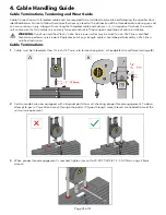
Страница 37: ...tallation WARNING Use of non certified techs note Service warranties may be void if a non Life Fitness certified technician performs service work Replacement of any strength cables should be performed by a Life Fitness certified technician Cable Terminations 1 Cable must be threaded at least inch 12 7mm into termination points at headplate A and frame carriage B 2 Certain models are now equipped w...

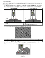
Страница 38: ...plate comes to rest on the weight plate below Check that the cable s threaded plugs are engaged at least 1 2 12 7mm at each termination point SEATED HEAD PLATE SUSPENDED HEAD PLATE 1 No gap 1 Gap 2 Bayonet obstructing weight stack pin 2 Ensure that the weight stack selector pin can fully engage into each weight plate Item Description Qty 1 Weight Stack Selector Pin 1 3 When proper thread engagemen...

Страница 39: ...cable twisting should be replaced immediately BULGING Internal wire rope strands can break within and coil causing a bulge to appear Cable should retain same outside diameter throughout FRAYED EXPOSED WIRE ROPE Any exposed wire rope protruding through the casing or at either end FLATTENED Section of cable is compressed and will not retain its shape outside diameter PERMANENTLY BENT Cable has kink ...

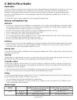
Страница 40: ...ver sub floor Dynamic anchors must have a minimum embedment depth in concrete to ensure maximum security and pull out force See Anchor Types for embedment depth minimums Building Codes It is the facility s responsibility to adhere to local and regional building codes Please verify with the customer to ensure that they are aware of this Carpeting If bolted down to carpet flooring be sure to use a b...

Страница 41: ...Tension KH EZ x 4 830 lb HUS H 6MM x 120MM 3 3 kN KH EZ 3 8 x 4 1535 lb KH EZ 3 8 x 5 1535 lb HUS H 8MM x 120MM 3 3 kN HUS H 8MM x 150MM 3 3 kN HSL 3 M 8 40 2000 lb HST M12 x 115 20 8 kN HST M12 x 195 200 8 kN KB TZ 3 8 x 3 3 4 1615 lb Design strength extracted from the Hilti Anchor Fastening Technology Manual issued September 2014 Tools Required WARNING Adhere to manufacturer s equipment warnings...

Страница 42: ...ccounted for refer to Anchor Selection and Foot Dimensions 4 Insert fastener and tighten to 18 Foot Pounds 24Nm for 1 4 6mm anchor or 40 Foot Pounds 54Nm for 3 8 8mm anchor NOTE If the legs frame do not contact the mounting surface DO NOT pull down with the fastener or anchor Loosen frame hardware and re tighten to allow machine to align Page 40 of 41 ...

Страница 43: ...Foot Dimensions Use below image to determine foot specifications Page 41 of 41 ...

Страница 44: ......

Отзывы: