2
21
7
2
8
1
I
17
4
G
F
1
3
H
8.
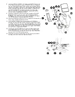
Locate the DISPLAY CONSOLE (4). Position the CONSOLE near the top
of the CONSOLE BRACKET. Attach all CONNECTORS (F & G) leading
from the CONSOLE BRACKET to their corresponding CONNECTORS in
the back of the DISPLAY CONSOLE. Feed any excess WIRE HARNESS
into the CONSOLE BRACKET and place the DISPLAY CONSOLE onto
the CONSOLE BRACKET aligning the mounting holes. Secure the
DISPLAY CONSOLE using four SCREWS (2). Tighten the SCREWS
securely. Do not over-tighten the SCREWS.
9.
Locate the CONSOLE SUPPORT COVER (8). Position the CONSOLE
BRACKET COVER over the underside of the CONSOLE SUPPORT
ASSEMBLY (7) as shown and secure it using two SCREWS (2). Tighten
the SCREWS securely. Do not over-tighten the SCREWS.
10.
Locate the CONSOLE SUPPORT CAP (21). Snap the CAP into position at
the top of the CONSOLE SUPPORT COVER.
11.
Locate the BASE FRAME CAP (19). Remove the two SCREWS (J)
securing the front of the BASE FRAME COVER (K) to the BASE FRAME
(L). Position the CAP over the front of the BASE FRAME as shown sliding
the mounting tabs to the inside of the BASE FRAME COVER. Secure the
CAP using two SCREWS (J) previously removed. Tighten THE SCREWS
securely. Do not over-tighten the SCREWS.
12.
Locate the four FOOT COVERS (20). Align the COVERS with the ends
of the STABILIZER BARS (M). Insert the post on the underside of the
FOOT COVERS into the mounting holes on the top of each STABILIZER.
Press the FOOT COVERS firmly into position.
13.
Position the unit into the desired location for use. Properly level the unit
according to the instructions in the Operation Manual.
J
20
M
K
L
19
Содержание 90X
Страница 1: ...95Xi 93X 90X Total Body Trainers Assembly Instructions...
Страница 7: ......


