HAL
Operation manual
OPERATION INSTRUCTIONS
This chapter describes the use of the complete range of HAL200 bullfloats.
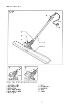
TIP:For the location and description of the bullfloat’s parts, which are mentioned in the
text, we refer to the illustration figure 1 on the backside of the cover.
HOW TO ASSEMBLE THE HAL 200 BULLFLOAT.
When delivered the bullfloat is not ready for use.You only have to carry out the following
procedures.
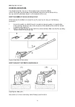
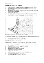
1
Connect the switch ( an ON/OFF-switch, an electronic speed regulator, or a gasthrottle),
to the operating handle by means of the bracket and the butterfly nut.Now lock the bracket
by tightning the butterfly nut.
2
Stick the operating handle into the shaft of the motorunit-frame.Make sure that the operating
handle is locked in the proper way.
Figure 2 Assembly of the controls.
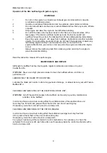
HOW TO ADJUST THE TROWEL BLADE ANGLE.
Adjusting the blade pitch
Use position (1) when smoothening normal freshly poured concrete.
6
Содержание HAL B Honda
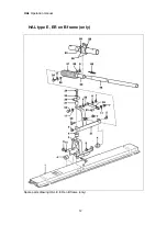
Страница 12: ...HAL Operation manual HAL type E ER en B frame only Spare parts drawing HAL E ER en B frame only 12...
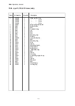
Страница 14: ...HAL Operation manual HAL type E ER Drive unit Spare parts drawing HAL E ER drive unit 14...
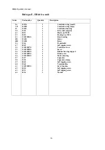
Страница 16: ...HAL Operation manual HAL type E ER Drive unit Switch Spare parts drawing HAL E ER Drive unit switch 16...
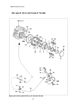
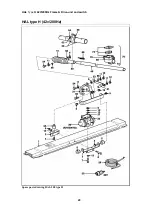
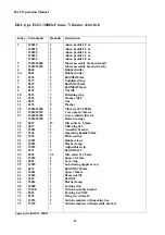
Страница 20: ...HAL Type H 42V 200Hz Frame Drive unit and switch HAL type H 42v 200Hz Spare parts drawing HAL 200 type H 20...


