Liebert GXT3-5000/6000RT208
SL-23188_REV1_08-10
10
Guide Specifications
2.4
BYPASS
2.4.1 General
A bypass circuit shall be provided as an integral part of the UPS. The bypass shall have a make-before-break
transfer, shall have a maximum detect and transfer time of 4-6 milliseconds and shall be a double-pole device.
The bypass circuit shall be designed to ensure the simultaneous transfer of the L1 and L2 poles. The bypass shall
be configured to wrap around the PFC converter, battery charger, DC-DC converter, inverter and battery. The
bypass circuit shall use the rear-panel mounted UPS input circuit breaker and route bypass power through the
UPS input filters and surge suppression circuit. The bypass circuit default position shall be in the Bypass mode
(utility).
2.4.2 Automatic Transfers
The transfer control logic shall activate the bypass automatically, transferring the critical AC load to the bypass
source, after the transfer logic senses one of the following conditions:
UPS overload
UPS overtemperature
PFC failure
Inverter failure
DC bus overvoltage
Once the overload condition is reduced, the load shall be automatically transferred back to inverter power. An
overtemperature requires manual transfer back to inverter power after cooling.
2.5
INTERNAL BATTERY
Valve-regulated, non-spillable, lead acid cells shall be used as a stored-energy source for the specified UPS
system. The battery kit shall be internal to the UPS cabinet and sized to support the inverter at rated load and
power factor with an ambient temperature of 77°F (25°C) for a minimum of 5 minutes reserve time. The expected
life of the battery shall be 3-5 years or a minimum 250 complete discharge cycles at ambient temperature of 77°F
(25°C). To promote battery service life and eliminate over-discharge of the battery, the end-of-discharge DC
shutdown voltage shall be automatically adjusted by the microprocessor based upon the percentage load at the
onset of battery operation.
2.6
OUTPUT DISTRIBUTION
Output distribution shall be integral to the UPS cabinet and located on the rear of the unit. The output distribution
shall provide the capability to re-configure the UPS input and output connections via a removable sheet metal
power distribution box. Distribution options shall be available with break-before-make maintenance bypass
switch to allow for complete shutdown and isolation of the UPS for service without powering down the
connected loads. Maximum transfer time of the maintenance bypass switch shall be 4-6ms. Standard output
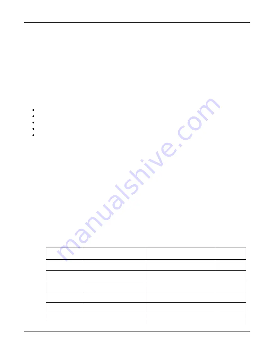
distribution configurations shall be:
Distribution
Model
Utility Input
Connection
Output Load Connections
Maintenance
Bypass
PD2-HDWR
Hardwire Terminals,
3-wire-plus-ground, 8AWG max
Hardwire Terminals,
3-wire plus Ground, 8AWG max
None
PD2-HDWR-MBS
Hardwire Terminals,
3-wire-plus-ground, 8AWG max
Hardwire Terminals,
3-wire plus Ground, 8AWG max
Included
PD2-001
NEMA L14-30P
NEMA L6-30R, (1) NEMA L14-30R,
(4) 5-20R (T-Slot)
Included
PD2-002
NEMA L14-30P
NEMA L6-20R,
(2) 5-20R (T-Slot)
Included
PD2-003
NEMA L14-30P
(2) NEMA L6-30R,
(4) 5-20R (T-Slot)
Included
PD2-004
NEMA L14-30P
(4) 5-20R (T-Slot), (2) L5-30R
Included
PD2-005
NEMA L14-30P
(4) L5-20R, (2) L6-30R
Included


