background image

Содержание Privilege GR-L207

Страница 1: ...trical components when replacing them 7 Make sure the hook is correctly engaged Remove dust and foreign materials from the housing and connecting parts 8 Do net fray damage machine heavily bond pull out or twist the power cord 9 Please check the evidence of moisture intrusion in the electrical components Replace the parts or mask it with insulation tapes if moisture intrusion was confirmed 10 Do n...

Страница 2: ...I 2002 08 24 245114 3 CIRCUIT DIAGRAM BASIC DELUXE _ _ PWBASSEMBLY MAIN _ PWBASSEMBLY MAIN 1 _ W 4LL 0_L_T m u_11_ AISItW m 5 c5 ...

Страница 3: ...7 GR L207 Cover Hinge Cover PWB t t t _ Freezer Refrige_r Compartme_ Compartm_t Shelf optional Box Shelf Steel T Glass Drawer or Shelf optional Drawe Shelf Door rack Conversion Switch Meats Vegetables Humidity Switch drawer Meat drawer 15 ...

Страница 4: ... O O 1 22 i 1 Q 1 23 i Q O 4th Press Q Temperature Medium Medium Max Max Min Medium Min Control Freezer Control 19 C 22 C 23 C 15 C 17 C Refrigeration 3 C 2 C 0 C 6 C 4 C Control t _ o The ICmpcralurecan _y 3 C dependingon the load condition P Whenever pressing button setting is repeated in the order of Medium Medium Max Max Min Medium Min The actual inner temperature varies depending on the food ...

Страница 5: ... In power application of refrigerator the only Release text is turned on at the right side of lock graphic of LCD with the lock release status 2 If desiring to lock the display status and pressing the lock release button once Release text is turned off at the right side of lock graphic of LCD and Lock text is turned on with lock status 3 The only buzzer sound rings and function is not performed ev...

Страница 6: ...g compressors and freezing room fan If pressing the special freezing button Turn Off text of the LCD panel is turned off and Turn On is immediately turned on end Arrow C _graphic is turned on after flickedng once 2 Special freezing is cycled in order of Selection Release Turn On Turn Oft whenever pressing the selection button 3 Special freezing is released if power failure occurs and then returns ...

Страница 7: ...tor performs ON OFF control by linking with the COMP 2 It controls at the single RPM withe_ varying RPM 3 Failure sensing method is same as in fan motor of fi eezing fan motor refer to failure diagnosis function table for failure display 2 10 Door opening alarm 1 Buzzer generates alarm sound if doors are not closed even when more than a minute consecutively has passed with doors of freezing cold s...

Страница 8: ...tion Sequence Remark When temperature of a frost removal sensorbecomes more thes 25 C in purchase rnovem_t J_ When _ temperature of a 5 frost removal _ sensorbecomes less than 25 C _ In powerfalture _ service Test mode 1 Compulsory func_es Testmode 2 Compulsory frost removal m i m r I 0 5 0 3 F FAN 0 3 STEP 0 3 HOME POWER sec COMP sec sec MOTOR sec BAR C FAN DAMPER HEATER ON ON ON ON ON i 05 FROST...

Страница 9: ...r dH Er FF Er OF Er CO Selfingtemperature display Note 1 Settingtemperature display Note2 Se_ng temperature display Note2 Contents of failure Snappingof shott drcult of freezer sensor Snapping or shott_ircuit of refrigeratorsensorI Snapping or short drcuit of refiigerator sensor2 Snapping or shott circuit of frost removal sensor Snapping of froat removal heater or temperature fuse ppl_ oatof conne...

Страница 10: ...ction adjustment button is not perceived during performance of test mode but only warning sounds ring 4 In finishing test mode always pull the power cord out and then plag in it again for the normal state 5 If nonconforming contents such as sensor failure are found dudng performance of test mode release the test mode and display the failure code 6 Even if pressing the test button during failure co...

Страница 11: ...Water is automaticel y turned off However the solenoid duct door is stop 5 seconds after Off to prevent short circuit of a coil due to overheat of solenoid 5 Dispenser Lamp On Off function Lamp on the dispenser part is turned on if pressing the dispenser press switch after selecting ice cube ice crushed ice or water If detaching the hands it is turned off 6 Selection function of water crushed cube...

Страница 12: ...EXPLATION FOR MICOM CIRCUIT 3 PWB parts diagram and list 3 1 PWB Ass y main part diagram 1 GR P247 L247 P207 L207 50 ...

Страница 13: ...0004_04_9_ _ mD 1N4004 I O E_T I_ _ J 1N44304 C_A_ 41 _ _ II_B IO_ 1N 00 1 es a 9 4_ 0_36000_ _ 0_01 D3SBA6O _ _01 tl lc_ 10 12 15J 10_ 43 _0_414_I SIIIOIIIG01_I IN4148 _ _ _Lor V_L_ _ Hm ITf NO WG NO IESI_I10_ Sp_ MAKER I 45 i 7_291F63_ 22 x_Fi16_ _5 461C8071P_38 _ 0_K_I_ 100_ 25_ Rug_t_t_ C 9 1 7 1_10_1_38 IuF 50V CE8 SSOuF 25V _E3 48 c_ mo Lrue_m t_ 1 _9 IEF 2_B_ 4690 Z20OUFt 25V S_ _ E4 1 50 _...

Страница 14: ... 13607015 UMP _Rf O 6XlOmm JCR2 JCR3 JCR4 _ 3607015 lUMp _RE 0 6XlOmm OP1 3607015 _JMP _RE 0 6XlOrnm HI H _ H_ 106 107 108 109 110 111 112 I_0 ElCe7A rS T_ m 7_z_ac 6200J_ CV940050 TNC L1 _k_ C0L 6200JB_07_ CV_10150 T_C l_mHi1A i 2 113 Ot_tSO_ _ CGt _O JH FNC L3 _ 114 3J024_7C F LJ SE 15A 250V FUSE1 11_ _901JB8001 FUgE _ F C 6 1 F AM JU 116 0_3001 _ F L J SE 2A 250V FUSE2 117 118 OO01030F 250 TAE ...

Страница 15: ... SPREAD SHEET RLDD6 3 46 5 S WAFER SMAWZS0 04 MICOM CHIP TMP47C42ZN KIA78LOSF REGULATOR KIA78SOSP KIA704ZAF ESET IC KIA704 2P V_LTA_IE I_ECTO_ BMR OIO1B KRAI06S TRANSISTOR KRClO6S KTA1298 RESONATOR CSTB 4 00MBW ELE CAPACITOR 330uF 25V SD 85 C E_ CAPACITOR IOOuF 16V GC 85 C TuF 25V CHIP CAPACITOF 104 50V 1608 ZOOJ I rW 3216 20J 1 BW 2012 1KJ 1 8W 2012 2KJ I SV _2O1 _ TKJ I SW Zm 2 15KJ 1 BW 2012 IM...

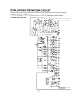
Страница 16: ...3 4 DISPLAY circuit diagram 1 GR P247 L247 P207 L207 RTO R71_ RESET OP1 Parts without I mark means SMD parts 58 ...

Страница 17: ...EXPLATION FOR MICOM CIRCUIT 4 PWB circuit diagram PWB circuit diagram may vary a little bit depending on actual condition 1 GR P247 L247 P207 L207 60 ...

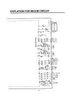
Страница 18: ...EXPLATION FOR MICOM CIRCUIT L T E _ _ _ p_ _ TE I 2 t _ t_ L w _ __ T_ 61 ...

Страница 19: ...EXPLODED VIEW FREEZER DOOR PART GR P247 GR P207 GR L247 GR L207 116 ...

Отзывы: