


20
Fn key combinations
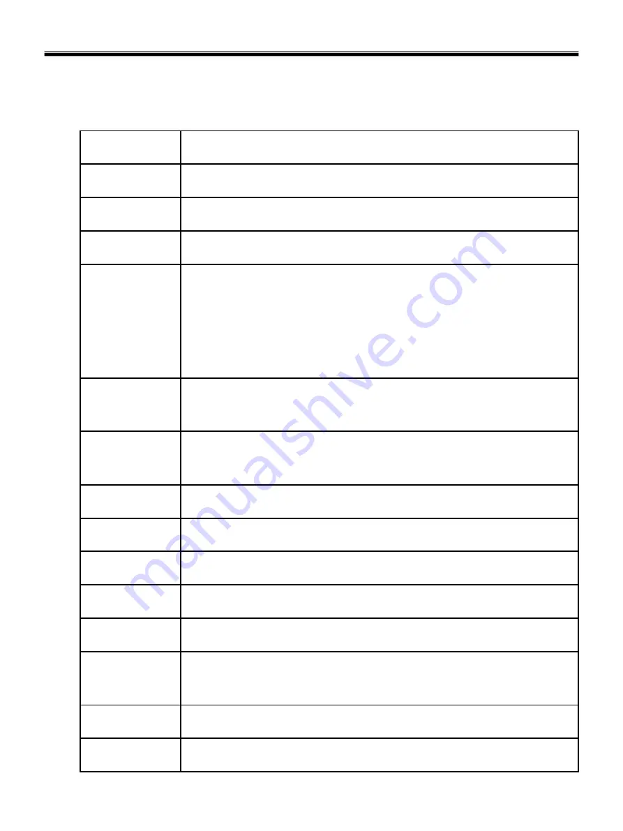
The following table shows the function of each combination of Fn with a function key.
Function of Fn keys has nothing to do with Operating System.
Ch3. System information
Darken the LCD Nine steps are available.
[Fn]+[▼]
Brighten the LCD Nine steps are available.
[Fn]+[▲]
Keys with square mark are enabled.
“
.Del
”
key functions as an Insert key while Num Lock is off.
[Fn]+[Num Lk]
Maximum power-saving mode (When OSD is installed).
[Fn]+[F12]
Fan control function CPU Cooling Fan control mode (Normal / Slow / Fast)
[Fn]+[F11]
Shows System information
[Fn]+[F10]
Mute(Sound On / Off)
[Fn]+[F9]
Power scheme change (Refer to the Battery Miser)
[Fn]+[F8]
Monitor toggle. When the computer is attached to an external monitor, you can
change the display output location with [Fn] + [F7] combination.
[Fn]+[F7]
Wireless LAN, Bluetooth On/Off.
Setting is available at OSD. The default is set to Wireless LAN, Bluetooth On/Off.
[Fn]+[F6]
Press the combination keys each time for Touchpad Enable / Touchpad Disable /
Touchpad Auto-dasable.
In Touchpad Auto-disable mode, Touchpad is disabled while USB or PS2 mouse is
connected.
Press again to change touchpad modes.
[Fn]+[F5]
Force the computer to enter power-saving mode. (ex: system standby or hibernation)
[Fn]+[F4]
User defined Hot key. (Setting is available at OSD)
[Fn]+[F3]
User defined Hot key. (Setting is available at OSD)
[Fn]+[F2]
User defined Hot key. (Setting is available at OSD)
[Fn]+[F1]
Содержание P1
Страница 2: ...0 Service Manual S1 P1 LG Electronics ...
Страница 21: ...19 System Block Diagram Ch3 System information ...
Страница 31: ...29 Ch3 System information c Select File Format as Image Files iso d Open Image File iso which is sent from LGE ...
Страница 32: ...30 Ch3 System information e Tab Next then burning will be started f Burn process completed as below and tab OK ...
Страница 59: ...57 2 Pull the HDD Assy out in the direction shown below Ch5 Removing and replacing a part ...
Страница 61: ...59 2 Disconnect the WLAN Card Antenna cable then remove the WLAN Card Ch5 Removing and replacing a part ...
Страница 63: ...61 3 Disconnect the keyboard connector Ch5 Removing and replacing a part ...
Страница 65: ...63 Ch5 Removing and replacing a part ...
Страница 68: ...66 Ch5 Removing and replacing a part ...
Страница 72: ...70 Ch5 Removing and replacing a part ...
Страница 76: ...74 3 Remove 5 screws 5 M2 5 x L6 0 1SZZBA4080J 1 Qty Specification FRU No No Ch5 Removing and replacing a part ...
Страница 77: ...75 4 Remove the Cardbus 5 in 1 Dummy Ch5 Removing and replacing a part ...
Страница 79: ...77 Ch5 Removing and replacing a part ...
Страница 81: ...79 3 Remove the Fan Assembly 2 Disconnect the Fan Assembly connector Ch5 Removing and replacing a part ...
Страница 83: ...81 3 Remove the Main Board Ch5 Removing and replacing a part ...
Страница 86: ...84 3 Remove the Audio sub board Ch5 Removing and replacing a part ...
Страница 88: ...86 2 Remove the Finger Printer Ch5 Removing and replacing a part ...
Страница 90: ...88 2 Remove the Touchpad Ch5 Removing and replacing a part ...
Страница 92: ...90 2 Disassemble the LCD Hook located on top of LCD Ch5 Removing and replacing a part ...
Страница 93: ...91 3 Remove a screw 1 M2 5 x L4 5 1SZZBA4080F 1 Qty Specification FRU No No Ch5 Removing and replacing a part ...
Страница 97: ...95 Ch5 Removing and replacing a part ...
Страница 106: ...Rocky W EXPLODED VIEW 2 NSCRC NBRKH NSCRC NCSNH NHDD1 NLAN1 NCVRC NMEM1 NCVRS ...
Страница 113: ...Rocky W EXPLODED VIEW 9 NSCR2 NSCR2 NSCR2 NSCR2 NSUBB NSUBT NSUBF NSUBA NSCR2 ...
Страница 118: ...Rocky W EXPLODED VIEW 14 NSCR7 NSCR7 NFAN1 NSCRA NFAN2 NSCR7 NMDM1 NCPU1 NMEM1 ...


