background image

39

ENG

English

Using PCoIP solution


y

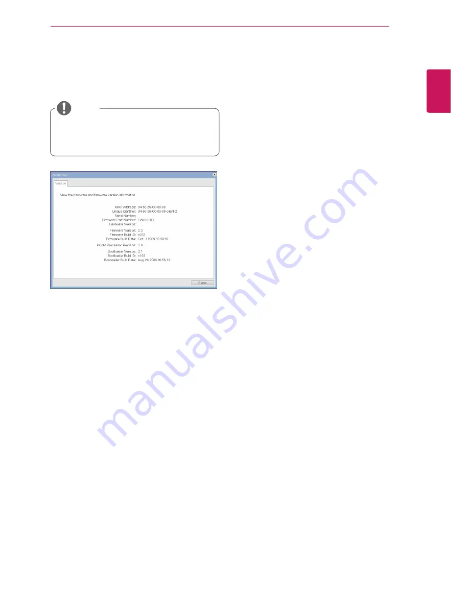
VPD Information

The Vital Product Data (VPD) is information that 
uniquely identifies each portal or host.


y

MAC Address

The portal MAC address


y

Unique Identifier

The portal ID


y

Serial Number

The portal serial number


y

Firmware Part Number

The part number of the PCoIP firmware


y

Hardware Version

The portal hardware version


y

firmware Information

The Firmware Information shows the details of the 
current PCoIP firmware.


y

Firmware Version

The current PCoIP firmware version


y

Firmware Build ID

The current PCoIP firmware revision code


y

Firmware Build Date

The current PCoIP firmware build date


y

boot loader Information

The Boot Loader Information shows the details of 
the current PCoIP boot loader.


y

Boot Loader Version

The current PCoIP boot loader version


y

Boot Loader Build ID

The current PCoIP boot loader revision code


y

Boot Loader Build Date

The current PCoIP boot loader build date


y

boot loader Information

The Boot Loader Information shows the details of 
the current PCoIP boot loader.


y

Mouse


y

Keyboard


y

Image


y

Display Topology

Figure 2-21. Version Configuration

Information Window

In the Information window, the administrator can 
access the Version tab that contains the device 
related information.

User settings Window

In the User Settings window, the administrator can 
access the tab to select the mouse and keyboard 
and define the PCoIP image quality.
The User Settings window has the following tabs:

PCoIP Processor Revision

This shows the PCoIP processor's revision code. 
TERA1x00 Revision A silicone is denoted by 0.0 
and TERA1x00 Revision B silicone is denoted by 
1.0.


y

The version information can also be viewed 
using the Webpage Administration Interface.

noTE

Содержание N2311AZ

Страница 1: ...www lg com Owner s Manual Network Monitor N2311AZ Please read the safety information carefully before using the product Network Monitor Model English ...

Страница 2: ...t plate 11 Mounting on a wall 13 USING THE MONITOR SET 13 Connecting Input Signal Cable 13 D SUB IN connection PC 13 D SUB OUT connection PCoIP 14 DVI connection PCoIP 15 Connecting LAN Peripherals 15 LAN connection PCoIP 16 Peripheral device connection 17 Self Image Adjustment 18 CUSTOMIZING SETTINGS 18 Accessing The Main Menus 19 MENU Settings 19 Picture 20 Color 21 Display 21 Volume Only suppor...

Страница 3: ...e an approved LG power adapter y y Damage caused by other power adapters is not covered by warranty y y Note that the components may look different from those shown here y y Without prior notice all information and specifications in this manual are subject to change to improve the performance of the product y y To purchase optional accessories visit an electronics store or online shopping site or ...

Страница 4: ...G English ASSEMBLING AND PREPARING Parts and buttons Power Indicator y y LED On Power is on y y LED Off Power is off Front Side Buttons Input Connectors See p 13 to 16 Power Button Input Connectors See p 16 ...

Страница 5: ...timal Resolution 1920 x 1080 INPUT Allows selection of the input signal y y If you connect the monitor to a computer using a D SUB cable select either the PCoIP or D SUB input signal y y The initial input signal is D SUB EXIT Exits the OSD menu Power Button y y D SUB Input Power On Off y y PCoIP Input Monitor Off Press the power button once then the monitor will be turned off after 5 seconds PCoIP...

Страница 6: ...monitor y y Avoid touching the screen at all times as this may result in damage to the screen or pixels CAUTION y y It is recommended to move the Monitor in the box or packing material that the Monitor originally came in y y Before moving or lifting the Monitor disconnect the power cord and all cables y y Hold the top and bottom of the Monitor frame firmly Make sure not to hold the transparent par...

Страница 7: ...d below y y Be careful not to touch or press the screen area when adjusting the angle of the monitor Warning Mounting on a table 1 Lift the monitor and place it on the table in an upright position Install at least 10 cm away from the wall to ensure sufficient ventilation 2 Connect the adaptor to the monitor then plug the power cord into the wall outlet 3 Press the Power button on the front of the ...

Страница 8: ...ensington lock is optional The accessories can be purchased at your local electronics store Note y y Once the pin is removed it is not necessary to re insert it to adjust the height Adjusting the stand height 1 Place the monitor mounted on the stand base in an upright position 2 Remove the tape attached at the bottom rear of the stand body then pull out the locking pin 3 The height can be adjusted...

Страница 9: ...ing in damage or injury y y To avoid damaging the screen when lifting or moving the monitor only hold the stand or the plastic cover This avoids putting unnec essary pressure on the screen y y Only remove the tape and the locking pin when the monitor is mounted on the stand base and is in an upright position Otherwise the stand body may protrude which may lead to injury Detaching the stand base 1 ...

Страница 10: ...ion Using the Pivot function The pivot function allows you to rotate the screen 90 degrees clockwise 2 Landscape Portrait You can rotate the panel 90 clockwise Please be cautious and avoid contact between the monitor head and the Stand Base when rotating the screen to access the Pivot function If the monitor head touches the Stand Base then the Stand Base could crack Head section Stand section 3 B...

Страница 11: ...4 mm 31 0 inch and above Please use VESA standard wall mount pad and screws Mounting on a wall Install the monitor at least 10 cm away from the wall and leave about 10 cm of space at each side of the monitor to ensure sufficient ventilation De tailed installation instructions can be obtained from your local retail store Please refer to the manual to install and set up a tilting wall mounting brack...

Страница 12: ...ct warranty y y Use the wall mounting bracket and screws that conform to the VESA standard Dam age caused by the use or misuse of inap propriate components will not be covered by the product warranty y y Use the screws specified in the VESA stan dard y y The wall mount kit includes the installation guide and necessary parts y y The wall mounting bracket is optional The accessories can be purchased...

Страница 13: ...itor to the PC using the provided 15 pin D SUB signal cable as illustrated below y y When using this device simply as a regu lar monitor through the RGB IN port set PCoIP to OFF in MENU OTHERS to reduce energy consumption Note Note RGB OUT RGB OUT RGB IN MONITOR D SUB OUT connection PCoIP D SUB OUT can only mirror the image displayed on the monitor it does not support an extended desktop Connect t...

Страница 14: ...ower cord to the out let use a grounded 3 hole multi socket or a grounded wall outlet y y The monitor may flicker when turned on in an area of low temperature This is normal y y Sometimes red green or blue spots may ap pear on the screen This is normal y y Connect the input signal cable and tighten in the direction of the arrow To prevent disconnection secure the cable tightly y y Do not press on ...

Страница 15: ... using a LAN cable as illustrated below y y The LAN cable is sold separately y y The following LAN cable type can be used Standard IEEE 802 3 ETHERNET y y If a device is connected into the earphone out port via a LAN cable you can adjust the volume with the volume icon on PC taskbar y y Connect the LAN cable and the peripheral devices prior to booting up the PC LAN Hub Router Note Note ...

Страница 16: ...angled plugs may have clear ance issues use straight plugs when pos sible Angle Type Straight Type Peripheral device connection Connect peripheral devices to the monitor using USB microphone and headphone ports Note Note y y Headphones speakers or microphone may not work normally depending on the server PC settings y y Virtual solutions may affect the functions or speed of the specific USB storage...

Страница 17: ...nd performs automatic image adjustment for each signal only available for analog D SUB input signals to provide an optimal screen display Self Image Adjustment Press the power button on the front to turn on the monitor When powered on the Self Image Adjustment function will run automatically only available for analog D SUB input signals Note ...

Страница 18: ...se the up arrow button 4 Select EXIT to leave the OSD menu MENU See p 19 Sets the screen options EXIT See p 5 Exits the OSD menu AUTO See p 23 Optimizes the resolution Disconnects from the server Different menu items are enabled depending on the type of input signal y y D SUB Input MENU AUTO INPUT EXIT y y PCoIP Input MENU VOLUME INPUT EXIT y y The language of the monitor s OSD menu and that of th...

Страница 19: ... items use the up arrow button Each option is explained below Menu Analog D SUB PCoIP Description BRIGHTNESS Sets the brightness of the screen CONTRAST Sets the contrast of the screen SHARPNESS Sets the sharpness of the screen y y If the screen is not displayed properly after adjusting the settings use the FACTORY RESET option to revert back to the factory default settings If necessary enable the ...

Страница 20: ... the clarity of the screen The gamma value can be set to 0 1 or 2 from darker to brighter screen colors respectively y y Analog D SUB analog signal input PCoIP Internal signal through the LAN Color 1 Press any button on the front of the monitor to dis play the MONITOR SETUP OSD menu 2 Press the MENU button to display the options in the OSD menu 3 Set the options by pressing the buttons on the fron...

Страница 21: ...signal through the LAN Display 1 Press any button on the front of the monitor to dis play the MONITOR SETUP OSD menu 2 Press the MENU button to display the options in the OSD menu 3 Set the options by pressing the buttons on the front of the monitor 4 Select EXIT to leave the OSD menu To return to the upper menu or set other menu items use the up arrow button Each option is explained below Volume ...

Страница 22: ...white balance adjusts the output signal level to correspond to that of the standard signal thus providing optimal display Run this option when the screen displays an image with both white and black FACTORY RESET Resets the screen to the factory default settings Note that the language option will not be reset y y Analog D SUB analog signal input PCoIP Internal signal through the LAN Others 1 Press ...

Страница 23: ...e If you are not satisfied with the optimized screen you can manually adjust the position of the display area frequency phase and sharpness in the OSD menu Only available for D SUB analog signals Note that the sharpness setting is only available for digital sig nals PROCESSING AUTO IMAGE ADJUSTMENT FOR OPTIMAL DISPLAY CHANGE RESOLUTION TO 1920 x 1080 y y What is Auto Image Adjustment The Auto Imag...

Страница 24: ...The OSD LOCKED message is displayed Is the OSD LOCKED message displayed when the MENU button is pressed y y The OSD lock feature is enabled to prevent undesired modification of the OSD settings Press and hold the MENU button for a couple of seconds to unlock the OSD The OSD UNLOCKED message will be displayed The screen retains an image Does image sticking occur even when the monitor is turned off ...

Страница 25: ...rred text a dimmed screen a truncated display area or misalignment of the display y y The configuration procedure may differ depending on your computer and or operating system Also some video cards may not support certain resolutions If this is the case contact the computer or video card manufacturer for assistance y y The AUTO option is only available for D SUB analog signals The display color is...

Страница 26: ...10 100 1000Mbps RJ45 PCoIP Power 19 V 2 3 A Power Consumption PCoIP D SUB On Mode 40 W 25 W Typical Power Saving Mode 16 W 1 W Off Mode 1 W AC DC Adapter Type PA 1650 68 manufactured by LITE ON TECHNOLOGY CORPORATION OUTPUT 19 V 3 42 A Dimension Weight Monitor Size Width x Height x Depth With Stand 548 2 mm x 476 7 mm x 224 4 mm Without Stand 548 2 mm x 334 9 mm x 54 8 mm Weight Without Packaging ...

Страница 27: ...ertical Frequency Hz Polarity H V Remark 720 x 400 31 468 70 08 640 x 480 31 469 59 94 800 x 600 37 879 60 317 1024 x 768 48 363 60 1280 x 1024 63 981 60 02 1680 x 1050 65 290 59 954 1920 x 1080 67 5 60 Recommended Mode Power Indicator Mode LED Color On Mode Red Power Saving Blinking Red Off Mode Off ...

Страница 28: ...ak every hour y y The stand is designed to best support the monitor when the optimal conditions are selected Adjust the angle of the monitor from 5 to 15 to obtain the best view of the screen You should be looking slightly down at the screen Place your hands gently on the keyboard keeping your arms bent at the elbows and extended horizontally in front of you Adjust the angle from 5 to 15 so that t...

Страница 29: ...e network is not ready Figure 2 3 shows the network icon when ready Figure 2 1 OSD Connect Screen Figure 2 4 OSD Connect Screen Connecting Figure 2 3 Network Ready Detail Connect Screen The Connect screen is shown during start up except when the portal has been configured for a managed start up or auto reconnect The logo dis played above the Connect button can be changed by uploading a replacement...

Страница 30: ...this field is required If DHCP is enabled this field cannot be edited This field must contain the correct IP address If an incorrect IP address is provided an OSD message is displayed prompting the administrator to provide the correct the IP address y y Subnet Mask The Subnet Mask field contains the subnet mask of the device If DHCP is disabled this field is required If DHCP is enabled this field ...

Страница 31: ...al The default value is PCoIP host MAC or PCoIP portal MAC where MAC is the MAC address of the host or portal If there is a domain name it will be added to the FQDN in the format of PCoIP host MAC domain local y y PCoIP Device Name In the PCoIP Device Name field the administrator can specify a logical name to the host or portal The default value is PCoIP host MAC or PCoIP portal MAC where MAC is t...

Страница 32: ...ed prompting the adminis trator to correct the error y y The Connection Management parameters can also be configured using the Webpage Administration Interface y y Enable Connection Management If the Enable Connection Management option is enabled the device can be controlled and config ured from an external connection manager y y Identify Connection Manager By The Identify Connection Manager By se...

Страница 33: ...strator can configure a portal for the PCoIP session or the RDP session y y Identify Peer By The Identify Peer By selector allows the adminis trator to decide whether to identify the peer device by IP by MAC address or by FQDN Table 2 2 shows the peer ID parameters that can be used with one of the two methods If an incor rect IP address or DNS name is provided an OSD message is displayed prompting...

Страница 34: ...ayout field allows the administrator to modify the keyboard layout Figure 2 11 RDP Configuration Figure 2 12 Language Configuration RDP Tab The RDP tab allows the administrator to configure the remote desktop protocol RDP specific set tings Language Tab The Language tab allows the administrator to set the OSD language y y The RDP Label parameters can also be con figured using the Webpage Administr...

Страница 35: ...s to the factory default settings When this button is pressed an OSD message is displayed This is to prompt the administrator and prevent accidental reset Figure 2 13 OSD Configuration Figure 2 14 Reset OSD Tab The OSD tab allows the administrator to modify the On Screen Display OSD parameters Reset Tab The Reset tab allows the administrator to reset all configurable parameters stored in Flash y y...

Страница 36: ...cally connects to the VMware View Connection Server when starting the portal y y Event Log y y Session Statistics y y PCoIP Processor y y Ping Each tab has the Close button to close the window Figure 2 15 Display Configuration Figure 2 16 VMware View Configuration Display Tab The Display tab allows the user to configure the EDID function of the monitor Diagnostics Window In the Diagnostics window ...

Страница 37: ... of PCoIP packets received from the host to the portal in the last active session y y PCoIP Packets Lost The PCoIP Packets Lost field shows the total number of PCoIP packets lost in the last ac tive session Figure 2 17 Event Log Configuration Figure 2 18 Session Statistics Configuration Event Log Tab The Event Log tab allows the administrator to view and delete the event log messages from the port...

Страница 38: ...o perform a ping test to the device and check if it can reach the overall IP network This is useful to check whether the device can reach the host y y The PCoIP Processor Uptime can also be viewed using the Webpage Administration Interface y y The Ping tab has no corresponding menu in to the Webpage Administration Interface of Section 1 Note y y Bytes Statistics y y Bytes Sent The Bytes Sent field...

Страница 39: ...ersion The current PCoIP boot loader version y y Boot Loader Build ID The current PCoIP boot loader revision code y y Boot Loader Build Date The current PCoIP boot loader build date y y Boot Loader Information The Boot Loader Information shows the details of the current PCoIP boot loader y y Mouse y y Keyboard y y Image y y Display Topology Figure 2 21 Version Configuration Information Window In t...

Страница 40: ... OSD and RDP session s keyboard repeat setting y y The OSD mouse cursor speed setting does not affect the mouse cursor settings when a PColP session is active unless the Local Keyboard Host Driver function is being used see PColP Host Software User Guide for more information y y The Mouse tab has no corresponding menu in the Webpage Administration Interface of Section 1 y y The OSD keyboard settin...

Страница 41: ...e may be preferred In environments where the network bandwidth is limited moving the slider towards Reduced en sures higher frame rates moving the slider towards Perception Free ensures higher image quality When network bandwidth is not limited the PCoIP system will maintain percep tion free quality regardless of the Minimum Image Quality setting Figure 2 24 Image Image The Image tab allows a user...

Страница 42: ...model and serial number of the SET is located on the back and one side of the SET Record it below should you ever need service As an ENERGY STAR Partner LGE U S A Inc has determined that this product meets the ENERGY STAR guidelines for energy efficiency ENERGY STAR is a set of power saving guidelines issued by the U S Environmental Protection Agency EPA ...

Отзывы: