


132 | GUIDELINES
MUL
TI V Ceiling Cassette Indoor Unit Engineering Manual
'XHWRRXUSROLF\RIFRQWLQXRXVSURGXFWLQQRYDWLRQVRPHVSHFL¿FDWLRQVPD\FKDQJHZLWKRXWQRWL¿FDWLRQ
©
/*(OHFWURQLFV86$,QF(QJOHZRRG&OLIIV1-$OOULJKWVUHVHUYHG³/*´LVDUHJLVWHUHGWUDGHPDUNRI/*&RUS
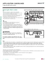
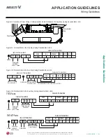
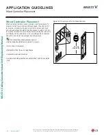
1. Insert the power wiring / communications cable from the outdoor unit or heat recovery unit (Heat Recovery systems only) using the desig-
nated path in the indoor unit.
2. Connect each wire to its appropriate terminal on the indoor unit control board. Verify that the color and terminal numbers from the outdoor
unit or heat recovery unit (Heat Recovery systems only) wiring match the color and terminal numbers on the indoor unit.
3. Secure the power wiring / communications cable.
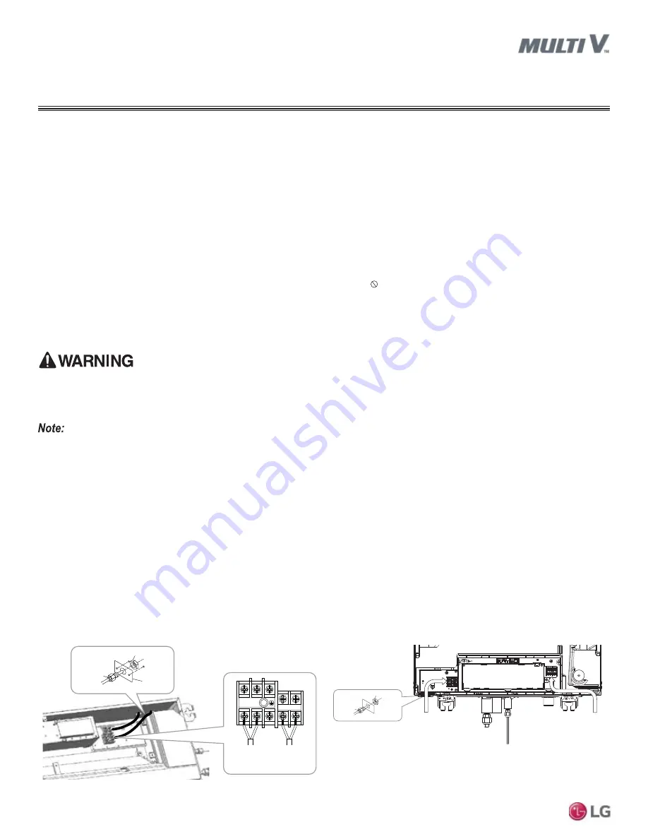
Power Wiring and Communications Cable Connections
Figure 108: Location of Power Wiring / Communications Cable Terminals
in the One-Way Ceiling-Cassette Indoor Unit.
Figure 109: Location of Power Wiring / Communications Cable Termi-
nals in the Two-Way Ceiling-Cassette Indoor Unit.
General Power Wiring / Communications Cable Guidelines
• Follow manufacturer’s circuit diagrams displayed on the inside of the control box cover.
• Have a separate power supply for the indoor units.
• Provide a circuit breaker switch between the power source and the indoor unit.
• Confirm power source specifications.
• Confirm that the electrical capacity is sufficient.
• Starting current must be maintained ±10 percent of the rated current marked on the name plate.
• Confirm wiring / cable thickness specifications:
• Power wiring is field supplied. Wire size is selected based on the larger MCA value, and must comply with the applicable local and
national codes.
• Communication cable between Master ODU to IDUs / HRUs to be 18 AWG, 2-conductor, twisted, stranded, shielded. Ensure the com-
munication cable shield is properly grounded to the Master ODU chassis only. Do not ground the ODU to IDUs / HRUs communication
cable at any other point. Wiring must comply with all applicable local and national codes.
• It is recommended that a circuit breaker is installed, especially if conditions could become wet or moist.
• Include a disconnect in the power wiring system, add an air gap contact separation of at least 1/8 inch in each active (phase) conductor.
• Any openings where the field wiring enters the cabinet must be completely sealed.
•
7HUPLQDOVFUHZVPD\ORRVHQGXULQJWUDQVSRUW3URSHUO\WLJKWHQWKHWHUPLQDOFRQQHFWLRQVGXULQJLQVWDOODWLRQRUULVNHTXLSPHQWPDOIXQFWLRQRU
SURSHUW\GDPDJH
.
•
/RRVHZLULQJPD\FDXVHXQLWPDOIXQFWLRQWKHZLUHVWREXUQRXWRUWKHWHUPLQDOWRRYHUKHDWDQGFDWFKILUH7KHUHLVDULVNRIHTXLSPHQWPDO
-
IXQFWLRQRUSURSHUW\GDPDJH
.
$YROWDJHGURSPD\FDXVHWKHIROORZLQJSUREOHPV
•
0DJQHWLFVZLWFKYLEUDWLRQIXVHEUHDNVRUGLVWXUEDQFHWRWKHQRUPDOIXQFWLRQRIDQRYHUORDGSURWHFWLRQGHYLFH
•
&RPSUHVVRUZLOOQRWUHFHLYHWKHSURSHUVWDUWLQJFXUUHQW
•
7HUPLQDOVFUHZVPD\ORRVHQGXULQJWUDQVSRUW3URSHUO\WLJKWHQWKHWHUPLQDOFRQQHFWLRQVGXULQJLQVWDOODWLRQRUULVNHOHFWULFVKRFNSK\VLFDO
LQMXU\RUGHDWK
•
/RRVHZLULQJPD\FDXVHWKHZLUHVWREXUQRXWRUWKHWHUPLQDOWRRYHUKHDWDQGFDWFKILUH7KHUHLVDULVNRIHOHFWULFVKRFNSK\VLFDOLQMXU\RU
GHDWK
1(L1) 2(L2)
3(A)
4(B)
Power Supply
High Voltage
(208/230V)
Communications
Lock nut
Conduit
mounting
plate
Conduit
APPLICATION GUIDELINES
Wiring Guidelines
Lock nut
Communication Cable /
Remote Controller Wiring
Conduit
Power Wiring


