- 14 -
4-3
Adjustment of White Balance
(1) Required Equipment
Color Analyzer( CA-100 or same product)
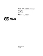
(2) Connecting diagram of equipment for measuring.
If you are adjusting a MZ Model, Use the RCA to SCART(Out)
cable to input a AV signal.
(3) Adjustment of White Balance
O
Operate the zero-calibration of the CA-100, then stick sensor
to PDP module surface when you adjust..
O
For manual adjustment, It is also possible by the following
sequence.
1) Select white pattern of heat-run mode by pressing power
on ket on remote control for adjustment then operate heat
run more than 15 minute.
2) Supply Gray Pattern(216 Gray full window) signal to
VIDEO input.(RZ-42PM10: AV4 input) refer to [fig3]
3) To adjust High Light, stick sensor to 216 Gray level
pattern, press ADJ key twice(White Balance) on remote
control.
For adjustment and
D
/
E
on remote control for adjustment
mode to select Red Gain and Blue Gain, press Vol +.-key
and adjust it ontil color coordination becomes as below.
[RF-04GA:RZ-42PM10]:
X; 0.283
¡
¡
æ
0.003, Y; 0.297
¡
¡
æ
0.003,
Color Temperatuer;9,300
¡K
¡
¡
æ
500
¡K
4) Exit adjustment mode using
V
Key.
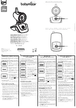
4-4 Auto Adjustment Map(RS-232C)
5. DDC Data Input
5-1. Required Test Equipment
(1) A jig for adjusting PC, DDC (PC serial to D-sub
Connection equipment)
(2) S/W for writing DDC (EDID Data Write & Read)
(3) D-sub 15P Cable, D-Sub to DVI Connector (Connect to
DVI Jack)
5-2. Setting of Device
5-3. Preparation for Adjustment
(1) Set devices as above and turn the PC, jig on.
(2) Put S/W for writing DDC (EDID data Write & Read) into
operation. (operated in DOS mode.)
5-4. Sequence of Adjustment
(1) DDC Data Input for Analog-RGB
1) Put the set on the table and turn the power on.
2) Connect PC Serial to D-sub 15P Cable of jig for DDC
adjustment to RGB terminal (D-Sub 15Pin).
3) Operate S/W for DDC record and select DDC data for
Analog RGB in Model Menu.
4) Operate EDID Write command.
5) Operate EDID Read command and check whether
Check Sum is OK.
6) If Check Sum is NG, repeat 3) ~ 4).
7) If Check Sum is OK, DDC data for Analog-RGB input is
completed.
(2) DDC Data input for Digital-RGB(DVI)
1) Connect PC Serial to DVI Cable of jig for DDC
adjustment to DVI terminal (DVI Jack).
2) Operate S/W for DDC record and select DDC data for
digital RGB in model menu.
3) Operate EDID Write command.
4) Operate EDID Read command and check whether
Check sum is OK
5) If Check sum is NG, repeat 3) ~ 4).
6) If Check sum is OK, DDC data for Analog-RGB input is
completed.
PC
JIG
PDP
SET
[Fig. 3] White Balance Adjustment
Window
Pattern
AV Signal I nput
COL OR
ANAL YZER
TYPE; CA-100
High L ight Adj ustor
(216 gr ay patter n)
MSPG-2100 or
MSTG-5200
RS-232C Ser ial Communication
Type
Baud Rate
115200
Index
R Gain
G Gain
B Gain
R Offset
G Offset
B Offset
Data bit
8
Cmd1
Cmd2
j
a
j
b
j
c
j
d
j
e
j
f
Stop bit
1
Parity
NONE
Protocol
Setting
Data
Min Value
00(00)
00(00)
00(00)
00(00)
00(00)
00(00)
Max Value
255(FF)
255(FF)
255(FF)
255(FF)
255(FF)
255(FF)
RF-043B_PDP42
Содержание MT-42PM10/B/HB
Страница 16: ... 16 1 2 Sony Power Board Structure T502 Vs Trans T702 Va Trans T101 St by Trans T103 Low Voltage Trans 1 2 3 ...
Страница 17: ... 17 1 3 Sanken Power Board Structure T221 Vs Trans T271 Va Trans T121 St by Trans T201 Low Voltage Trans 1 2 3 ...
Страница 26: ... 26 BLOCK DIAGRAM Cable ...
Страница 27: ... 27 BLOCK DIAGRAM Cable ...
Страница 36: ......
Страница 37: ......
Страница 38: ......
Страница 39: ......
Страница 40: ......
Страница 42: ...Feb 2005 Printed in Korea P NO 3828VD0198F ...