


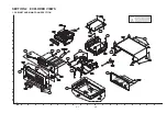


1-2
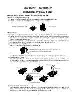
NOTES REGARDING HANDLING OF THE PICK-UP
1. Notes for transport and storage
1) The pick-up should always be left in its conductive bag until immediately prior to use.
2) The pick-up should never be subjected to external pressure or impact.
2. Repair notes
1) The pick-up incorporates a strong magnet, and so should never be brought close to magnetic materials.
2) The pick-up should always be handled correctly and carefully, taking care to avoid external pressure and
impact. If it is subjected to strong pressure or impact, the result may be an operational malfunction and/or
damage to the printed-circuit board.
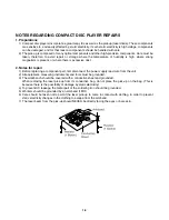
3) Each and every pick-up is already individually adjusted to a high degree of precision, and for that reason
the adjustment point and installation screws should absolutely never be touched.
4) Laser beams may damage the eyes!
Absolutely never permit laser beams to enter the eyes!
Also NEVER switch ON the power to the laser output part (lens, etc.) of the pick-up if it is damaged.
5) Cleaning the lens surface
If there is dust on the lens surface, the dust should be cleaned away by using an air bush (such as used
for camera lens). The lens is held by a delicate spring. When cleaning the lens surface, therefore, a cotton
swab should be used, taking care not to distort this.
6) Never attempt to disassemble the pick-up.
Spring by excess pressure. If the lens is extremely dirty, apply isopropyl alcohol to the cotton swab. (Do not
use any other liquid cleaners, because they will damage the lens.) Take care not to use too much of this
alcohol on the swab, and do not allow the alcohol to get inside the pick-up.
SERVICING PRECAUTIONS
SECTION 1 SUMMARY
Содержание MBD-D102X
Страница 7: ...1 6 MEMO ...
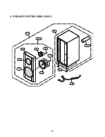
Страница 10: ...2 5 3 SPEAKER SECTION MBS D102V 750 751 752 754 755 757 A70A 758 A70 757A 759 756 753 ...
Страница 35: ...3 24 4 FOCUS WAVEFORM 1 FDO 2 F 3 F INSERT CD INSERT DVD 1 FDO 2 F 3 F ...
Страница 37: ...3 26 7 TRACKING SIGNAL 1 Tro 2 Tr 3 Tr 8 RF WAVEFORM ...
Страница 38: ...3 27 9 DISK TYPE JUGEMENT WAVEFORM 1 F 2 FDO 3 SVRRF DVD CD ...
Страница 50: ...3 39 7 MC4580 7 1 PIN CONFIGURATION 7 2 TEST CIRCUIT 7 3 ABSOLUTE MAXIMUM RATINGS TA 25 ...
Страница 60: ...3 49 3 50 WIRING DIAGRAM ...
Страница 62: ...3 53 3 54 2 MAIN FRONT BLOCK DIAGRAM ...
Страница 64: ...3 57 3 58 2 MAIN INTERFACE PWM SCHEMATIC DIAGRAM ...
Страница 65: ...3 59 3 60 3 MPEG SCHEMATIC DIAGRAM ...
Страница 66: ...3 61 3 62 4 SERVO SCHEMATIC DIAGRAM ...
Страница 67: ...3 63 3 64 5 INTERFACE SCHEMATIC DIAGRAM ...
Страница 68: ...3 65 3 66 6 FRONT SCHEMATIC DIAGRAM ...
Страница 69: ...3 67 3 68 7 FRONT MIC SCHEMATIC DIAGRAM ...
Страница 70: ...3 69 3 70 8 IPOD 1 SCHEMATIC DIAGRAM OPTION ...
Страница 71: ...3 71 3 72 9 IPOD 2 SCHEMATIC DIAGRAM OPTION ...
Страница 72: ...3 73 3 74 10 2 CHANNEL AMP SCHEMATIC DIAGRAM ...
Страница 73: ...3 75 3 76 11 BLUTHOOTH MODULE SCHEMATIC DIAGRAM OPTION ...
Страница 75: ...3 79 3 80 1 MAIN P C BOARD TOP VIEW PRINTED CIRCUIT BOARD DIAGRAMS ...
Страница 76: ...3 81 3 82 MAIN P C BOARD BOTTOM VIEW ...
Страница 77: ...3 83 3 84 2 FRONT P C BOARD TOP VIEW BOTTOM VIEW ...
Страница 78: ...3 85 3 86 3 SMPS P C BOARD TOP VIEW BOTTOM VIEW ...
Страница 79: ...3 87 3 88 MEMO 4 MIC JACK P C BOARD TOP VIEW BOTTOM VIEW 5 IPOD P C BOARD OPTION TOP VIEW BOTTOM VIEW ...