manualshive.com logo in svg
background image

3

ILUSTRACIONES DE INSTALACIÓN

IMPORTANTE 

GUÁRDELO PARA EL USO DEL INSPECTOR LOCAL DE INSTALACIONES ELÉCTRICAS.

HOLGURAS Y DIMENSIONES (Figura 1)

Consulte la figura 1 a continuación para la instalación de la estufa.

Si se va a instalar en CANADÁ, una estufa autónoma no podrá instalarse a menos de 12 mm de cualquier
superficie adyacente.

DIMENSIONES MÍNIMAS (Figura 2)

* 30”(76.2 cm) de holgura mínima entre la cubierta de la superficie de cocción y la base de un gabinete de

madera o de metal sin protección; o 24”(60.9 cm) como mínimo cuando la parte inferior de un gabinete
de madera o de metal está protegida por una capa de 

1

/

4

”(6.4 mm)  de cartón gris resistente al fuego y

recubierta cuando menos con lámina de acero no. 28 MSG , 0.015”(0.381 mm) de acero inoxidable,
0.024”(0.610 mm) de aluminio o 0.020”(0.508 mm) de cobre.

** 15” (38.1 cm) como mínimo entre la cubierta de los gabinetes y la parte inferior del gabinete adyacente.

2

FIGURA 1

FIGURA 2

A = 30” (76.2 cm) Para EE.UU.

= 30” (76.2 cm) ~ 31” (78.7 cm) Para CANADÁ
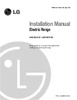
Sección 2

PREPARATIVOS PARA INSTALAR LA ESTUFA

PRECAUCIÓN

Esta estufa ha sido diseñada para

cumplir con las temperaturas máximas permitidas para
gabinetes de madera, es decir 194°F (90°C). Cerciórese de
que los recubrimientos de la pared, cubierta y gabinetes
alrededor de la estufa pueden resistir la temperatura
generada por la estufa (194°F (90°C)). De lo contrario podría
presentarse decoloración, derretimiento o delaminación.

IMPORTANTE

Para eliminar los riesgos de

quemaduras o incendios cuando se trata de alcanzar algo
por encima de unidades con superficies calientes, debe
evitarse disponer de gabinetes de almacenamiento por
encima de las unidades de superficie. Si se han provisto
gabinetes de almacenamiento, puede reducirse el riesgo si
se instala una campana de estufa que sobresalga un mínimo
de 5 pulgadas (12 cm) de la parte inferior de los gabinetes.

Содержание LRE30451

Страница 1: ...InstallationManual Electric Range LRE30451S LRE30755S Please read these instructions thoroughly before installing and operating the range P No 3828W5U0512 Website http us lge com ...

Страница 2: ... before installing range Remove all packing materials from the oven compartments before connecting the electrical supply to the range Observe all governing codes and ordinances Be sure to leave these instructions with the consumer Important Note to the Consumer Keep these instructions with your owner s manual for future reference As when using any appliance generating heat there are certain safety...

Страница 3: ...024 0 610 mm aluminum or 0 020 0 508 mm copper 15 38 1 cm minimum between countertop and adjacent cabinet bottom 2 FIGURE 1 FIGURE 2 A 30 76 2 cm For U S A 30 76 2 cm 31 78 7 cm For CANADA Part 2 PREPARE TO INSTALL THE RANGE CAUTION This range has been designed to comply with the maximum allowable wood cabinet temperatures of 194 F Make sure the wall covering countertop and cabinets around the ran...

Страница 4: ...ce must be installed and grounded on a branch circuit by a qualified technician in accordance with the National Electrical code ANSI NFPA NO 70 latest edition All wiring should conform to Local and NEC This range requires a single phase 3 wire A C 120 208V or 120 240V 60Hz electrical system Use only a 3 conductor or a 4 conductor UL listed range cord with closed loop terminals open end spade lugs ...

Страница 5: ...d or 3 wire conduit has to be connected to the middle post of the main terminal block The remaining two wires of the power cord or conduit have to be connected to the outside posts of the main terminal connection block WARNING Only a 4 conductor power supply cord kit rated 120 240 volts 50 amperes and marked for use with ranges with closed loop connectors open end spade lugs with upturned ends sha...

Страница 6: ...ts securely onto the terminal block 5 Go to page 8 Install the conduit as follows Remove the Conduit connection plate from the rear of drawer body and rotate it as shown in Figure 8 The conduit hole 11 8 must be used First prepare conduit cord as shown in Figure 9 Second install conduit cord as shown in Figure 10 For conduit installations after purchasing a strain relief insert it in the conduit h...

Страница 7: ... used connect with adapter lugs as shown in Figures 11 and 13 3 Insert the end of green wire ground from conduit into the lug and tighten the clamping screw Attach the lug to the GND hole below terminal block with ground screw removed earlier 4 Insert the end of each wire L1 L2 Neutral into each separate lug Tighten the clamping screw 5 Remove the 3 nuts from the terminal block Remove the ground s...

Страница 8: ... with the appliance See instructions to install supplied with bracket Unless properly installed the range could be tipped by stepping or sitting on the door Injury may result from spilled hot liquids or from the range itself 8 Use a spirit level to check your adjustments Place the level diagonally on the oven rack and check each direction for level First check direction 1 After check direction 2 I...

Страница 9: ...nualdeinstalación Estufa eléctrica LRE30451S LRE30755S Sírvase leer cuidadosamente estas instrucciones antes de instalar y poner a funcionar la estufa Número de pieza 3828W5U0512 Sitio Web http us lge com ...

Страница 10: ...or Notas importantes para el consumidor Conserve estas instrucciones junto con su manual del propietario para cualquier consulta en el futuro Al igual que cuando se utiliza cualquier artefacto que genera calor deben seguirse ciertas precauciones de seguridad Cerciórese de que su estufa sea instalada y conectada a tierra correctamente por un instalador o técnico de servicio calificado Cerciórese de...

Страница 11: ...omo mínimo entre la cubierta de los gabinetes y la parte inferior del gabinete adyacente 2 FIGURA 1 FIGURA 2 A 30 76 2 cm Para EE UU 30 76 2 cm 31 78 7 cm Para CANADÁ Sección 2 PREPARATIVOS PARA INSTALAR LA ESTUFA PRECAUCIÓN Esta estufa ha sido diseñada para cumplir con las temperaturas máximas permitidas para gabinetes de madera es decir 194 F 90 C Cerciórese de que los recubrimientos de la pared...

Страница 12: ...CTRICAS REQUISITOS DE LAS CONEXIONES ELÉCTRICAS Este artefacto deberá instalarse y conectarse a tierra en un circuito de red por un técnico certificado de acuerdo con la edición más reciente del código de la National Electrical code ANSI NFPA NO 70 Todo el alambrado deberá conformarse a Local y NEC Esta estufa requiere de un sistema eléctrico monofásico de 3 alambres 120 208 V C A o 120 240 V 60Hz...

Страница 13: ...ble de alimentación o conducto portacables de 3 alambres debe conectarse al poste central del bloque de terminales principal Los dos alambres restantes del cable de alimentación o conducto portacables de 3 alambres deberán conectarse a los postes externos del bloque de terminales principal ADVERTENCIA Use solamente un cable de alimentación de 4 alambres con capacidad nominal de 120 240 voltios 50 ...

Страница 14: ... Quite la placa de conexión de conductos portacables de la parte posterior del cuerpo del cajón y déle vuelta como se muestra en la figura 8 Debe usarse el orificio de conducto portacables 11 8 3 cm Primero prepare el cable del conducto portacables tal como se muestra en la figura 9 Seguidamente instale el cable del conducto portacables tal como se muestra en la figura 10 Para las instalaciones de...

Страница 15: ...se muestra en las Figuras 11 y 13 3 Inserte el extremo del alambre verde tierra del conducto portacables en la orejeta y apriete el tornillo de apriete Afiance la orejeta al orificio GND debajo del bloque de terminales con el tornillo de tierra que retiró anteriormente 4 Inserte el extremo de cada alambre L1 L2 Neutral en cada orejeta separada Apriete el tornillo de apriete 5 Quita las 3 tuercas d...

Страница 16: ...ula Si no se instaló correctamente la estufa podría volcarse si se pisa o se sienta en la puerta Podrían producirse lesiones por el derrame de líquidos calientes o por la estufa misma 8 Utilice un nivel de burbuja para verificar sus ajustes Coloque el nivel en la parrilla del horno de la estufa en forma diagonal y verifique el nivel en cada dirección Primero verifique la dirección 1 Después verifi...

Отзывы: