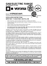
background image

GAS/ELECTRIC RANGE

for residential use only

THIS RANGE IS FOR RESIDENTIAL USE ONLY

FOR INSTALLER ONLY

Some  models  are  supplied  with  a  protective  film  on  steel  and  aluminium 

parts. This film must be removed before installing/using the appliance.

Models:


VEFSGE304P..

INSTALLATION INSTRUCTIONS
IMPORTANT - PLEASE READ AND FOLLOW

•  Before beginning, please read these instructions completely and carefully.
•  Do not remove permanently affixed labels, warnings, or plates from the product. This may 

void the warranty.

•  Please observe all local and national codes and ordinances.
•  Please ensure that this product is properly grounded.

• 

The installer should leave these instructions with the consumer who should retain 

for local inspector’s use and for future reference.

Installation must conform with local codes or in the absence of codes, the National Fuel Gas 

Code ANSIZ223.1 - Iatest edition. Electrical installation must be in accordance with the Na-

tional Electrical Code, ANSI/NFPA70 - latest edition and/or local codes.

IN CANADA: Installation must be in accordance with the current CAN/CGA-B149.1 National 

Gas Installation Code or CAN/CGA-B149.2, Propane Installation Code and/or local codes.

Electrical installation must be in accordance with the current CSA C22.1 Canadian Electrical 

Codes Part 1 and/or local codes.
INSTALLATION IN MANUFACTURED (MOBILE) HOME: The installation must conform with 

the Manufactured Home Construction and Safety Standard, Title 24 CFR, Part 3280 [formerly 

the Federal Standard for Mobile Home Construction and Safety, Title 24, HUD (Part 280)] 

or, when such standard is not applicable, the Standard for Manufactured Home Installations, 

ANSI/NCSBCS A225.1, or with local codes where applicable.
INSTALLATION IN RECREATIONAL PARK TRAILERS: The installation must conform with 

state or other codes or, in the absence of such codes, with the Standard for Recreational 

Park Trailers, ANSI A119.5.
Installation of any gas-fired equipment should be made by a licensed plumber. A manual 

shut-off valve must be installed in an accessible location in the gas line external to the ap-

pliance for the purpose of turning on or shutting off gas to the appliance (In Massachusetts 

such shutoff devices should be approved by the Board of State Examiners of Plumbers & 

Gas Fitters).
If an external electrical source is utilized, the appliance, when installed, must be electrically 

grounded in accordance with local codes or, in the absence of local codes, with the national 

Electrical Code, ANSI/NFPA 70.

R

Summary of Contents for VEFSGE304P

Page 1: ...nstallation Code and or local codes Electrical installation must be in accordance with the current CSA C22 1 Canadian Electrical Codes Part 1 and or local codes INSTALLATION IN MANUFACTURED MOBILE HOME The installation must conform with the Manufactured Home Construction and Safety Standard Title 24 CFR Part 3280 formerly the Federal Standard for Mobile Home Construction and Safety Title 24 HUD Pa...

Page 2: ...arm the room Doing so may result in carbon monoxide poiso ning and overheating of the appliance WHAT TO DO IF YOU SMELL GAS Do not try to light any appliance Do not touch any electrical switch Do not use any phone in your building lmmediately call your gas supplier from a neighbor s phone Follow the gas supplier s instructions lf you cannot reach your gas supplier call the fire depart ment Install...

Page 3: ...nd in not suitable for any none domestic application and therefore should not be used in a com mercial environmement The appliance warranty will be void if the appliance is used within a none domestic environmement i e a semi commercial commercial or communal environment CONVERSION LABEL DATA PLATE ...

Page 4: ...perty damage Consult a quali fied installer service agent or the gas supplier Screwdriver 2 Wrench T handle wrench Tape measure Pencil Adjustable pliers Adjustable wrench Suitable protective gloves Drill Hammer TOOLS NEEDED FOR INSTALLATION NOT SUPPLIED WITH THE APPLIANCE IMPORTANT The use of suitable protective clothing gloves is recommended when handling installing of this appliance ...

Page 5: ...lly remove the range by pulling outward CAUTION Range is heavy use care in handling 10 Electrical Requirement Electrical installation should comply with national and local codes 11 Air Supply and Ventilation The installer must refers to local national codes 12 Gas Manifold Pressure Natural gas 4 0 W C P LP Propane 11 0 W C P 13 The misuse of oven door e g stepping sitting or leaning on them can re...

Page 6: ...er side vertical surfaces above 36 914 mm high There must be a minimum of 11 13 16 300 mm side clearance from the range to such combustible surfaces TO THE LEFT or TO THE RIGHT above the 36 914 mm high countertop IMPORTANT One side left or right above the 36 914 mm high countertop must always be kept clear Island installation There must be a minimum of 12 305 mm clearan ce from the rear of the bac...

Page 7: ...the 2 screws A interposing the spacers Screw the central screw B 1 Fig 1 3 GAS AND ELECTRIC CONNECTION Fig 1 2 Dotted line showing the position of the range when installed Area for ELECTRICAL connection Area for GAS connection B A B C C Ref inch mm A 5 7 16 6 1 8 138 155 5 B 14 3 8 365 C 37 64 14 5 Depending on feet regulation ...

Page 8: ... A PROXIMITY TO SIDE CABINETS STANDARD INSTALLATION Fig 1 4b Fig 1 4a OVEN VENT Ref inch mm A 0 0 B 36 914 C 11 13 16 300 D 30 minimum 762 minimum E 18 minimum 457 minimum F 13 maximum 330 maximum G 20 minimum 500 minimum OVEN VENT 1 ...

Page 9: ...ION A A B G E D F C H A A B G E D F C H Fig 1 5b Fig 1 5a OVEN VENT Ref inch mm A 0 0 B 36 914 C 11 13 16 300 D 30 minimum 762 minimum E 18 minimum 457 minimum F 13 maximum 330 maximum G 20 minimum 500 minimum H 12 minimum 305 minimum OVEN VENT 1 ...

Page 10: ...ear left foot slides under the anti tip bracket attached LEVELLING THE RANGE The range is equipped with 4 LEVELLING FEET and may be levelled by screwing or unscrewing the feet figs 1 6 1 7 It is important to observe the directions of figures 1 6 1 8a 1 8b Fig 1 8b Fig 1 8a Fig 1 7 Fig 1 6 Supplied with the range in a separate kit Supplied with the range in a separate kit 0 0 mm 5 16 8 mm 5 16 8 mm...

Page 11: ...emove the backguard 2 Remove the pan supports and the burner flame spreaders 3 Unscrew cooktop fixing screws A in figure below 4 Remove the dual burner inner flame spreader B in figure below 5 Remove the cooktop keep attention not to damage the gaskets fitted above the burner cups below the cooktop 6 Install the front guard C by inserting the wire terminals into the proper holes above the control ...

Page 12: ... must be made according to national and local codes This gas supply service line must be the same size or greater than the inlet line of the appliance Sea lant on all pipe joints must be resistant to the action of LP Propane gas The range is equipped for the use with NATURAL gas It is design certified by CSA Inter national for NATURAL and L P gases with appropriate conversion The model serial rati...

Page 13: ...h Do not over tighten the connector Over tightening may crack regulator STEP 2 Assemble the 1 2 NPT connector pressure regulator group to the extension pipe interposing the gasket supplied The regulator cover must be oriented toward the front side of the range IMPORTANT use two wrenches to tighten the connection Fig 2 3 Fig 2 2 Regulator cover Gasket ...

Page 14: ...e fitting To range 1 2 G cylindrical ISO 228 1 female Extension pipe 1 2 G cylindrical ISO 228 1 male Extension pipe male pipe fitting Gasket Connector 1 2 NPT conical male 1 2 NPT female Pressure regulator 1 2 NPT female To mains connection Arrow WARNING check the right positioning of the gas regulator The arrow on the back of the gas regulator must be oriented toward the connector ...

Page 15: ...lated from the gas supply piping system by closing its individual manual shut off valve during any pressure testing of the gas supply piping system at test pressure equal to or less than 1 2 PSI 3 5 kPa 3 Flexible Connections If local codes permit CSA or UL design certified flexible metal appliance connector is recommended for connecting this range to the gas supply line Do Not kink or da mage the...

Page 16: ...rked on the body of each injector SETTING THE PRESSURE REGULATOR fig 2 6 The pressure regulator is accessible by removing the warmer drawer the pressure regulator is positioned on the rear right side of the range fig 2 9 To remove the warming drawer 1 Open the drawer completely fig 2 6 2 Move down the lever of left guide fig 2 7 and up the lever of right guide fig 2 8 3 Remove the drawer the lever...

Page 17: ...r fig 2 9 1 Unscrew the regulator cover 2 Unscrew the A component reverse and screw it accor ding to the LP PROPANE regulation Fitting the warming drawer fig 2 10 1 Insert the drawer guides into the range guides fig 2 10 2 Gently close the drawer completely the safety catchs will be automatically hooked Fig 2 10 Fig 2 9 ...

Page 18: ...plate D and screw the no 2 fixing screws C then refit the inner crown flame spreader B and screw the no 3 fixing screws A Refit the flame spreaders the burner caps and the pan supports The burner are conceived in such a way so as not to require the regulation of the primary air SECOND ORIFICE DEUXIEME ORIFICE A A A B C C D J2 J3 Fig 2 12 J1 Fig 2 11 SEMI RAPID BURNER DUAL BURNER INJECTORS TABLE NO...

Page 19: ...inimum rate of inner crown Remove the knob With a thin screwdriver turn the regulation screw R2 until adjustment is correct Outside crown of DUAL burner Light the DUAL burner Set the gas valve to position minimum rate of inner and outer crowns Remove the knob With a thin screwdriver turn the regulation screw R3 until adjustment is correct For LP PROPANE gas tighten the adjustment screws completely...

Page 20: ...rectly to the fused disconnect or circuit breaker box through flexible counduit with copper or aluminium wiring with grounding wire Allow two to three feet of slack in the line so that it can be moved if servicing is ever necessary ELECTRICAL CONNECTION WITH POWER CORD Use a 3 wire power supply cord kit rated for 30 amps 240 208 120 volts with closed loop terminals and marked for use with ranges W...

Page 21: ...eck the correct positioning of the Power Cord Bracket as per figure 3 3 3 Assemble the strain relief in the hole on Power Cord Bracket 4 Insert the Power Cord through the strain relief and tighten 5 Remove the 3 wire terminal nuts and washers from the Termi nal Block 6 Remove the Ground Strap from the frame of range and termi nal by removing its screw and cutting it as shown in Figure 3 3 7 Plug t...

Page 22: ... as per figure 3 6 3 Feed 1 2 1 3 cm trade size Conduit through the hole in the Conduit Bracket and secure to the Conduit Bracket with a Conduit Clamp 4 Remove the 3 wire terminal nuts and washers from the Termi nal Block 5 Remove the Ground Strap from the frame of range and termi nal by removing its screw and cutting it as shown in Figure 3 6 6 Plug the terminal holes of conductors The Neutral Wi...

Page 23: ...23 3 WIRING DIAGRAM ...

Page 24: ...rors in the present booklet The manufacturer reserves the right to make all modifications to its products deemed necessary for manu facture or commercial reasons at any moment and without prior notice without jeopardising the essential functional and safety characteristics of the appliances Cod 1103877 ß1 ...

Reviews: