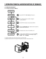
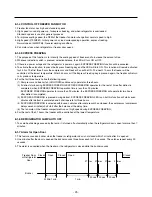

7-2-5 Function TEST
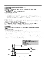
1. This is a compulsory operation for TEST, SVC, cleaning, etc. It is operated by pressing the water supply control KEY for 3 seconds.
2. It operates in the Ice Making mode, but not in the Ice-Removing mode or water supply process. (If there is an ERROR, it
can only be checked in the TEST mode.)
3. If the water supply control KEY is pressed for 3 seconds in the Ice-Making mode (no matter what condition the Ice-
Making tray is in) the Ice-Removing operation starts immediately. Water is not yet frozen, so water is poured instead of
ice. If the control doesn’t operate normally in the TEST mode, check and repair as needed.
4. After water is supplied, the normal CYCLE is followed:
ice making
→
Harvest
→
Fill
→
Park Position
.
5. When Stage 5 is completed in the TEST mode, minimize MICOM in 5 seconds, the time needed to supply water resets to
the previous status in the TEST mode.
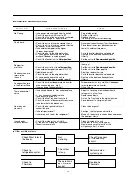
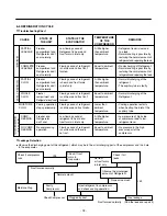
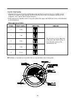
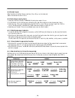
Diagnosis TABLE
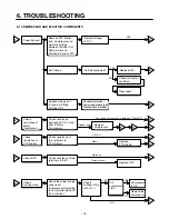
7-3 DEFECT DIAGNOSIS FUNCTION
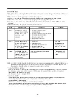
7-3-1 ERROR CODES shown on Ice Maker water supply control panel
ERROR indicators in table can be checked only in TEST mode.
-
23
-
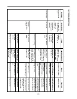
STAGE
ITEMS
INDICATOR
REMARKS
1
2
3
4
5
6
HEATER
MOTOR
HALL IC (detection
of position)
I
VALVE
HALL IC (detection
of full-filled Ice)
II
reset
Five seconds after heater starts, heater will
go off if temperature recorded by sensor is
10°C or lever is in up position.
Five seconds after heater starts, you can
confirm that motor is moving.
You can confirm Hall Ic detection of position.
Two seconds after detection of initial
position, you can confirm that valve is on.
You can check whether hall is sensing Full
ice condition. (If there is a full-filled error, the
fifth LED is not on.)
Five seconds after fifth stage is completed,
the icemaker reset at initial status.
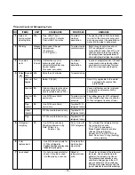
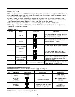
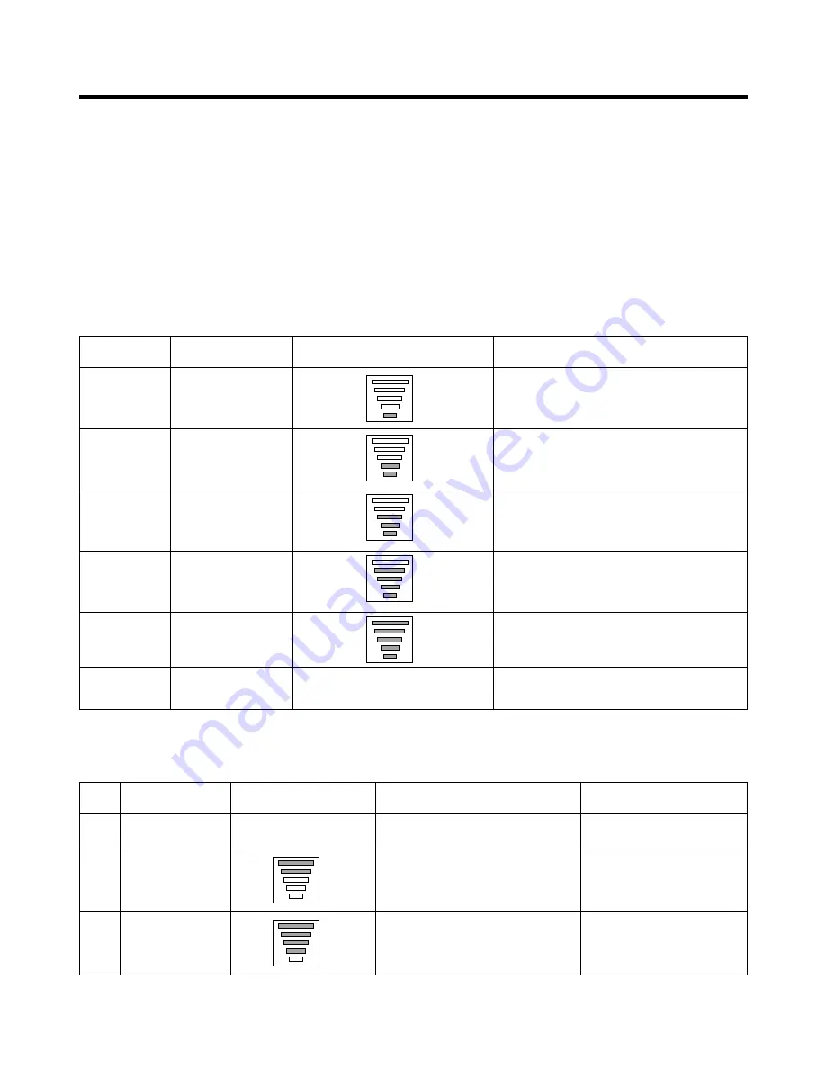
NO
DIVISION
INDICATOR
CONTENTS
REMARKS
1
2
3
Normal
Ice-Making
Sensor
malfunction
Ice Maker Kit
malfunction
Mark time to
supply
Mark previous status on TEST mode
None
Cut or short-circuited wire
When ejector blades don’t reach
park position over 18 minutes
since Harvest Mode starts.
Display switch
operates properly
Make sure that the wire
on each sensor is
connected.
Defects of
HALL IC/MOTOR/
HEATER/RELAY
Содержание LRBC22522
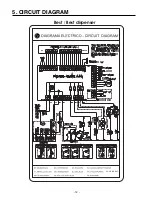
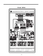
Страница 12: ...GY GRIS GRAY Best Best dispenser 5 CIRCUIT DIAGRAM 12 ...
Страница 13: ...GY GRIS GRAY Good Better 13 ...
Страница 40: ...8 5 MAIN PWB ASSEMBLY AND PARTS LIST 8 5 1 Main PWB Assembly 40 ...
Страница 41: ...8 5 2 Replacement Parts List 41 ...
Страница 42: ...8 5 3 PWB Assembly Display And Parts List 42 SW106 Dispenser Model Best Model ...
Страница 44: ... 44 FREEZER SENSOR FREEZER DOOR SWITCH REFRIGERATOR DOOR SWITCH REFRIGERATOR SENSOR DEFROST SENSOR 220 1 2W ...
Страница 60: ...9 5 MAIN PWB ASSEMBLY AND PARTS LIST 9 5 1 Main PWB Assembly 60 ...
Страница 61: ...9 5 2 Replacement Parts List 61 ...
Страница 62: ...9 5 3 PWB Assembly Display And Parts List 62 ...
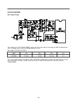
Страница 63: ...9 6 PWB DIAGRAM 9 6 1 PWB Main Assembly 63 G5S 1A RY5 ...
Страница 64: ... 64 ...
Страница 70: ...June 2009 ...


