background image

Your Safety First

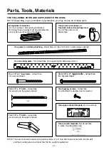
• MAKE SURE YOU HAVE ENOUGH SPACE AND SUPPORT.

– Mount the oven against a flat, vertical wall, so it is supported by the wall. The wall should be constructed of

minimum 2" x 4" wood studding and 3/8" thick drywall or plaster/lath.

– ATTACH (See note on page 

4

) the two lag screws supporting the oven to a vertical, 2" x 4" wall stud.

– DO NOT mount the microwave oven to an island or peninsula cabinet.

– BE SURE the upper cabinet and rear wall structures can support 150 lbs., plus the weight of any

items you place inside the oven or upper cabinet.

– Locate the oven away from strong draft areas, such as windows, doors, and strong heating vents.

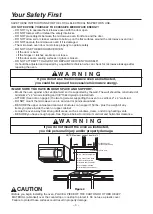
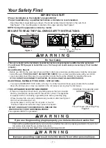
– BE SURE you have enough space. See Figure 4 below for minimum vertical and horizontal clearance.

 Before you begin installing the oven, PLACE A PIECE OF THE CARTON OR OTHER HEAVY

MATERIAL (a blanket) over the countertop or cooktop to protect it. Do not use a plastic cover.

Failure to protect these surfaces could result in property damage.

30" min. cabinet opening width

30" min. clearance from bottom

of cabinet to cooking surface

or countertop before installation.

Grounded Outlet

(inside upper cabinet)

Power Supply Cord Hole

(Use templates included

 with installation instructions)

If 

y

ou do not mount the 

o

ven as instructed,

y

ou risk personal injury and/or property dama

g

e.

NOTE: Maximum cabinet depth is 13".

SAVE THESE INSTRUCTIONS FOR THE LOCAL ELECTRICAL INSPECTOR'S USE.

• DO NOT EXPOSE YOURSELF TO EXCESSIVE MICROWAVE ENERGY!

– DO NOT try to operate the microwave oven with the door open.

– DO NOT tamper with or defeat the safety interlocks.

– DO NOT place objects between the microwave oven front face and the door.

– DO NOT allow soil or cleaner residue to build up on the flat surfaces around 

– DO NOT operate the microwave oven if it is damaged.

– The microwave oven door must close properly to operate safely.

– DO NOT USE THE MICROWAVE OVEN:

the microwave oven door.

 If the door is bent.

 If the hinges or latches are broken or loose.

 If the door seals, sealing surfaces or glass is broken.

– DO NOT ATTEMPT TO ADJUST OR REPAIR THE OVEN YOURSELF!

It should be adjusted and repaired by a qualified technician who can check for microwave leakage after

repairing the oven.

If 

y

ou do not use the micr

ow

ave 

o

ven as instructed,

y

ou could be exposed to excessive micr

ow

ave ener

gy

.

W A R N I N G

w

W A R N I N G

w

w

CAUTION

– 

3

 –

Figure 4

Содержание LMVM2033BM

Страница 1: ...Website http www lg com MICROWAVE OVEN INSTALLATION INSTRUCTIONS PLEASE READ AND SAVE THESE INSTALLATION INSTRUCTIONS MFL06206505 ...

Страница 2: ...tric current This appliance is equipped with a cord having a grounding wire with a grounding plug Place the plug into a properly installed and grounded outlet See Figure 3 Do not use an extension cord Keep the power cord dry and do not pinch or crush it Failure to follow this instruction may cause a fire hazard DO NOT UNDER ANY CIRCUMSTANCES REMOVE THE POWER SUPPLY CORD GROUNDING PRONG This applia...

Страница 3: ...untertop before installation Grounded Outlet inside upper cabinet Power Supply Cord Hole Use templates included with installation instructions If you do not mount the oven as instructed you risk personal injury and or property damage NOTE Maximum cabinet depth is 13 SAVE THESE INSTRUCTIONS FOR THE LOCAL ELECTRICAL INSPECTOR S USE DO NOT EXPOSE YOURSELF TO EXCESSIVE MICROWAVE ENERGY DO NOT try to o...

Страница 4: ...he damper duct connector One upper cabinet template Not Actual Size One rear wall template Not Actual Size 1 piece mounting plate only One power cord clamp bushing Actual Size for the cord hole in a metal upper cabinet NOTE You need to install at least one lag screws into a 2 x 4 stud and three anchor bolts into the wall and the mounting area must meet the 150 lbs weight requirement One One mounti...

Страница 5: ...or the power cord hole You will need the following tools and materials for the installation Carton or other heavy material such as a blanket for covering the counter top 3 8 and 3 4 wood drill bits 1 2 and 3 16 drill bits Electric Drill Small Side Cutters Nipper or Tin Snips If you have brick or masonry walls you will need special hardware and tools The ductwork you need for the installation is no...

Страница 6: ...o not have the proper wall outlet you MUST have one installed by a qualified electrician 2 You will cut the hole for the power supply cord shown in Figure 5 later when you prepare the wall and upper cabinet in Step 4 NOTE Do not use an extension cord Keep the power cord dry and do not pinch or crush it DO NOT UNDER ANY CIRCUMSTANCES REMOVE THE POWER SUPPLY CORD GROUNDING PRONG This appliance MUST ...

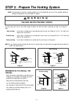
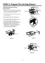
Страница 7: ... Figure 8 NOTE If you choose the rear exhaust method roof or wall venting be sure there is enough clearance within the wall for the exhaust duct REMEMBER AS YOU INSTALL THE VENTING Keep the length of the ductwork and the number of elbows to a minimum to ventilate your oven efficiently See examples on page 8 Keep the size of the ductwork the same Do not install two elbows together Use duct tape to ...

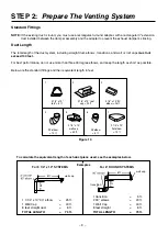
Страница 8: ...ee elbows and keep the length as short as possible Below are the standard fittings and their equivalent length in feet To calculate the equivalent length of each duct piece used see the examples below Figure 10 6ft 2ft 2ft wall cap 6ft transition wall cap For 3 1 4 x 10 SYSTEMS 1 3 1 4 x 10 90 elbow 25 ft 1 Wall Cap 40 ft 8 feet straight duct 8 ft TOTAL LENGTH 73 ft 1 transition 5 ft 2 90 elbows 2...

Страница 9: ... the exhaust adaptor the grease filters and the power supply cord ROOF VENTING INSTALLATION This oven is shipped assembled for roof venting 1 Insert the tabs on each side of the damper into the holes at the inside rear of the adaptor Attach the exhaust adaptor to the blower plate with the two tapping screws provided See Figure 12 Make sure that the damper swings freely A thick protective covering ...

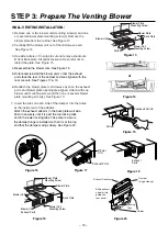
Страница 10: ...ower unit mounting screw and then one or several blower plate mounting screw s See Figure 19 7 Insert the tabs on each side of the damper into the holes at the inside rear of the adaptor Attach the exhaust adaptor to the back plate wall side Push in securely until it is past the top locking tabs and in the lower locking tabs Take care to assure the damper hinge is installed so that it is at the to...

Страница 11: ...attach blower plate to microwave oven Attach with the one blower unit mounting screw and then the one or several blower plate mounting screw s See Figure 25 Figure 21 Figure 25 Blower Plate Mounting Screw Blower Plate Back Plate Parts B Blower Unit Figure 23 Blower Unit Blower Unit Mounting Screw Blower Plate Mounting Screw Blower Plate Back Plate Blower Unit Mounting Screw Blower Unit Parts B 5 P...

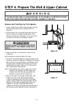
Страница 12: ... 27 4 Center the rear wall template in the space by lining up the plumb line on wall with centerline on template Then securely tape or tack the rear wall template in place Make sure the minimum width is 30 inches and that the top of the rear wall template is located a minimum of 30 inches above the cooking surface See Figure 26 NOTE If the cabinets are not plumb adjust the rear wall template to th...

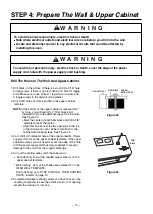
Страница 13: ...e If the upper cabinet is metal you will need to cover the edge of the hole with the power supply cord bushing supplied to prevent damage to the cord from the rough metal edge 4 Cut out the venting areas with the saber saw Roof Venting cut out the shaded area marked L on the upper cabinet template Room Venting go to STEP 5 INSTALL THE MOUNTING PLATE located on page 14 5 Complete whichever venting ...

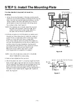
Страница 14: ...mplate to the cabinets If the front edge of the cabinet is lower than the back edge adjust the template to be level with the cabinet front a stud If there is a stud drill a 3 16 hole for lag screws If there is no stud drill a 5 8 hole for toggle bolts These holes must be used for mounting If the holes are not used the installation will not be secure Installer must use these holes for proper instal...

Страница 15: ... venting installation See Figure 34 Install ductwork through the vent opening in the upper cabinet Use caulking gun to seal the exterior roof opening around the exhaust cap See Figure 7 on page 7 5 Use the power supply cord clamp to bundle the power supply cord Install the power supply cord clamp using a screw as shown in Figure 35 to the inside of the cabinet 6 Grasp the filter screen with one ha...

Страница 16: ...Printed in China ...
Отзывы: