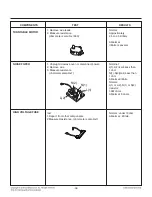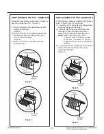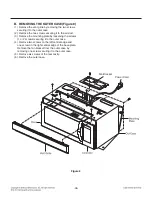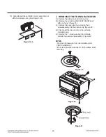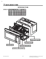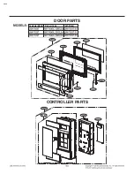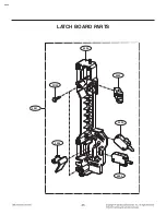
-29-
9-2. Interlock Continuity Test
A. PRIMARY INTERLOCK SWITCH TEST
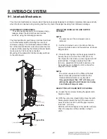
When the door is opened slowly, an audible click
should be heard at the same time or successively
at intervals and the latches should activate the
switches with an audible click.
If the latches do not activate the switches when
the door is closed, the switches should be
adjusted in accordance with the adjustment
procedure.
Disconnect the wire lead from the primary switch.
Connect the ohmmeter leads to the common
(COM) and normally open (NO) terminal of the
switch. The meter should indicate an open circuit
in the door open condition.
When the door is closed, the meter should
indicate a closed circuit.
If the primary switch operation is abnormal,
make the necessary adjustment or replace the
switch, making sure to replace it with the same
type of switch.
B. SECONDARY INTERLOCK SWITCH TEST
Disconnect the wire lead from the secondary
switch.
Connect the ohmmeter leads to the common
(COM) and normally open (NO) terminals of the
switch. The meter should indicate an open circuit in
the door open condition. When the door is closed,
the meter should indicate a closed circuit. If the
secondary switch operation is abnormal, make the
necessary adjustment or replace the switch, making
sure to replace it with the same type of switch.
C. MONITOR SWITCH TEST
Disconnect the wire lead from the monitor switch.
Connect the ohmmeter leads to the common
(COM) and normally closed (NC) terminals of the
switch. The meter should indicate a closed circuit in
the door open condition. If the door is closed, the
meter should indicate an open circuit. If the monitor
switch operation is abnormal, replace it with the
same type of switch.
NOTE: After repairing the door or the interlock
system, it is necessary to do this continuity
test before operating the oven.
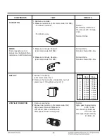
COMPONENTS
TEST PROCEDURE
RESULTS
SWITCHES
Check for continuity of the
Door
Door
(Wire leads removed)
switch with an ohmmeter
open
closed
Primary
Switch
Monitor
Switch
Secondary
Switch
NOTE : After checking for the continuity of the switches, make sure that they are
connected correctly.
WARNING : FOR CONTINUED PROTECTION AGAINST EXCESSIVE RADIATION
EMISSION, REPLACE ONLY WITH IDENTICAL REPLACEMENT PARTS.
TYPE NO.SZM-V16-FA-63 OR VP-533A-OF OR V-5230Q FOR PRIMARY SWITCH
TYPE NO.SZM-V16-FA-62 OR VP-532A-OF OR V-5220Q FOR MONITOR SWITCH
TYPE NO.SZM-V16-FA-63 OR VP-533A-OF OR V-5230Q FOR SECONDARY SWITCH
NO
COM
NC
COM
NO
COM
Содержание LMV1762SB
Страница 7: ... 7 4 OPERATION 4 1 Control Panel 12 14 15 17 23 20 16 21 22 19 13 2 3 1 6 7 9 11 8 10 4 5 18 ...
Страница 10: ... 10 5 2 Key Matrix KEY MATRIX KEY MATRIX ...
Страница 14: ... 14 6 4 Troubleshooting No Display or Dead ...
Страница 16: ... 16 Keypad Failure ...
Страница 43: ...OVEN CAVITY PARTS 3034 3010 3001 3029 6001 6000 3011 3025 3026 3028 3018 3036 3024 5138 3024 EV ...
Страница 44: ...W102 4000 4002 4003 4001 4004 4002 LATCH BOARD PARTS EV ...
Страница 46: ...INTERIOR PARTS II EV 5024 3027 5045 3028 5037 5038 5010 5001 W101 5058 5044 3004 5043 5006 5041 ...
Страница 47: ... EV INSTALLATION PARTS 6011 6010 6009 6008 MBM4 VINYL BAG Customer Model Product Code SVC Model ...
Страница 48: ......


