LG LM40 Скачать руководство пользователя страница 87

86

5. Press the hook on the both side of LCD with a (-) type screwdriver and remove from the LCD real panel.

Ch5. Removing and replacing a part

Содержание LM40

Страница 1: ...0 Service Manual LM40 50 LG Electronics ...

Страница 2: ...on System Block Diagram Fn key combinations Status indicators BIOS Flash BIOS Setup Ch 4 Symptom to part index Power system checkout Numeric error codes Error messages LCD related symptoms Indeterminate problems Ch 5 Removing and replacing a part FRU Ch 6 Part list Part list Exploded view Contents ...

Страница 3: ...er you are servicing may have been changed Be extremely careful during write operations such as copying saving or formatting If you select an incorrect drive data or programs can be overwritten Use the following strategy to prevent unnecessary expense for replacing and servicing parts 1 If you are instructed to replacing a part but the replacement does not correct the problem reinstall the origina...

Страница 4: ...hrow it into fire or water or short circuit it Dispose of the battery pack as required by local ordinances or regulations Use only the battery in the appropriate parts listing when replacing the battery pack Use of an incorrect battery can result in ignition or explosion of the battery Warning If the LCD breaks and the fluid from inside the LCD gets into your eyes or on your hands immediately was ...

Страница 5: ...ed covers and other parts in a safe place away from all personnel while you are servicing the machine Keep your tool box away from walk areas so that other people will not trip over it Do not wear loose clothing that can be trapped in the moving parts of a machine Make sure that your sleeves are fastened or rolled up above your elbows If your hair is long fasten it Insert the ends of your necktie ...

Страница 6: ...r before 1 Performing a mechanical inspection 2 Working near power supplies 3 Removing or installing main units Before you start to work on the machine unplug the power cord If you cannot unplug it ask the customer to power off the wall box that supplies power to the machine and to lock the wall box in the off position If you need to work on a machine that has exposed electrical circuits observe t...

Страница 7: ... look carefully for possible hazards in your work area Examples of these hazards are moist floors non grounded power extension cables power surges and missing safety grounds Do not touch live electrical circuits with the reflective surface of a plastic dental mirror The surface is conductive such touching can cause personal injury and machine damage Do not service the following parts with the powe...

Страница 8: ...rds such as loose or missing hardware Refer to the following checklist and begin the checks with the power off and the power cord disconnected Checklist 1 Check exterior covers for damage loose broken or sharp edges 2 Power off the computer Disconnect the power cord 3 Check the power cord for a A third wire ground connector in good condition Use a meter to measure third wire ground continuity for ...

Страница 9: ...he part from touching your clothing Most clothing retains a charge even when you are wearing a wrist strap 4 Use the black side of a grounded work mat to provide a static free work surface The mat is especially useful when handling ESD sensitive devices 5 Select a grounding system such as those listed below to provide protection that meets the specific service requirement Note The use of a groundi...

Страница 10: ...e DVD ROM drive or the other optical storage device could result in exposure to hazardous laser radiation There are no serviceable parts inside those drives Do not open Danger Emits visible and invisible laser radiation when open Do not stare into the beam do not view directly with optical instruments and avoid direct exposure to the bean 1 5 Backup Standby RTC battery safety information When repl...

Страница 11: ...cur for a variety of reasons that have nothing to do with a hard ware defect such as cosmic radiation electrostatic discharge or software errors Consider replacing a FRU only when a problem recurs If you suspect that a FRU is defective clear the error log and run the test again If the error does not recur do not replace the FRU Be careful not to replace a non defective FRU What to do first You mus...

Страница 12: ...age caused foreign material in the diskette drive Diskette drive damage caused by pressure on the diskette drive cover or by the insertion of a diskette with multiple labels Damaged or bent diskette eject button Fusses blown by attachment of a non supported device Forgotten computer password making the computer unusable Sticky keys caused by spilling a liquid onto the keyboard The following sympto...

Страница 13: ... button Built in speakers Volume Up Front view 15 Chapter 2 Locations Ch2 Locations Power saving mode switch IrDA port LCD Power switch Volume Down Keyboard TouchPad TouchPad button Built in speakers Volume Up Front view 14 1 Power saving mode switch IrDA port ...

Страница 14: ... 15 14 1 Security key hole Kensington Lock User can attach a separately purchased chain lock into the security keyhole and connect it to a fixed object to prevent a notebook theft S Video Modem port Power jack Ethernet port Emergency eject hole USB port Headphone jack S PDIF VGA port Parallel port Fan louvers PC card slot Rear view 15 14 1 Left view 15 14 1 ...

Страница 15: ...I Cardbus Socket SD Card Slot Memory Stick Slot ODD Fixed Optical Storage DVD COMBO Port VGA PIO 2X USB 2 0 1X USB 1 1 RJ11 RJ45 Headphone out S PDIF Mic in DC in IEEE1394 Input Devices Keyboard Full sized Keyboard 2 5mm Key Storke Touchpad 3 Buttons Power Volume Up Volume Down Indicator LED Power HDD Activity Caps Lock Num Lock Wireless LAN Battery Charge AC Power 65 Watt 18 5V Adapter Audio 2 Pr...

Страница 16: ...15 Model Configuration Ch3 System information ...

Страница 17: ...16 System Block Diagram Ch3 System information ...

Страница 18: ...r if it is installed To enable this function you have to install the Battery Miser first Switch between the computer display and an external monitor If an external monitor is attached computer output is displayed in the following three patterns by turns External monitor CRT display Computer display and external monitor LCD CRT display Computer display LCD Enable Disable TouchPad Disable TouchPad b...

Страница 19: ...c keys you must enable the Internal Keypad setting under the Advanced menu in the BIOS Setup Utility g Wireless activity indicator Wireless activity indicator indicates the following Blue The Wireless client is associated with the network Off The Wireless card does not have the power or RF is off Blinking The Wireless client is not associated with the network c Power Power status indicator indicat...

Страница 20: ...nsert the diskette into the FDD of your computer 5 Boot your computer with the diskette and type phlash16 wph mode n 6 Cold boot and follow the instruction displayed on the screen Flash options mode n 0 Default mode Keep the current DMI information and update BIOS image only 1 Update DMI information only If new DMI information is not specified the current DMI information is left unchanged 2 Update...

Страница 21: ...nter the name of the backup file for existing BIOS or click Browse to locate the file b Enter the name of the new BIOS file or click Browse to locate the file 5 Click Advanced Settings button to access the advanced settings 6 Click Flash BIOS button to start flash BIOS 7 Wait for the operation to complete WinPhlash may take one or two minutes to complete flash BIOS operation How to update flash RO...

Страница 22: ...dated appears on the screen then the computer restarts 9 After the restart make sure the system BIOS is updated 10 If your computer does not restart automatically turn off your computer and then turn it back on by pressing power button Ch3 System information ...

Страница 23: ...system environment hardware configurations power saving mode etc Open the BIOS Setup Utility in the following situations 1 to change the BIOS setup 2 to replace the backup battery 3 system configuration error occurs 4 to change the boot order 5 to set change a password Press the power button When the LG logo appears on the screen press and enter the BIOS Setup Utility Ch3 System information ...

Страница 24: ...nu enables you to configure the operating environment for peripheral devices such as legacy USB TouchPad internal keypad and parallel port Security menu enables you so set or change supervisor and user passwords Boot menu enables you to set the order of drives the system selects to find its operating system during the boot sequence Use Enter and keys to change the order Exit menu enables you to sa...

Страница 25: ...ted Select Menu Move to another menu Change Values Change the value of a selected item Load Default Configuration Display Setup Confirmation window Press Enter to load default configuration Select Sub Menu Some items have sub menus Display the sub menu for a selected item Save and Exit Display Setup Confirmation window Press Enter to save and exit Exit In a sub menu press Esc to move to the previo...

Страница 26: ...PU type and clock speed installed on the system BIOS Version KBC Version UUID Number Display BIOS KBC version information and UUID value Primary Master Secondary Master Display the information about the device used as the primary master Press Enter to set the parameters of the device at this connection System Memory Extended Memory Display the memory size information Ch3 System information ...

Страница 27: ...cy USB Support Enable support for the Legacy USB Enabled Disabled Internal Keypad Enable support for the internal keypad Enabled Disabled Ch3 System information TouchPad Support Enable support for TouchPad Enabled Disabled ...

Страница 28: ...sabled Ch3 System information Parallel port modes 1 Output only The normal mode Use this mode when you connect a printer to the parallel port 2 Bi directional Allows bi directional high speed data transfer 3 EPP Extended Parallel Port Allows a connection to a device supporting EPP EPP uses the existing parallel port signal to allow asymmetric bi directional data transfer with a host device 4 ECP E...

Страница 29: ...t have a password A supervisor password prevents unauthorized users from changing the system setup a Start the system setup utility and use arrow keys to select Set Supervisor Password under Security menu and then press Enter b If the following screen appears select Set Supervisor Password by using arrow keys and Enter Caution If you forget the password you cannot gain access to your system Make s...

Страница 30: ...sswords c If the following message appears enter a new supervisor password and then Enter A password must be consisted of character A Z and numbers 0 9 and have the maximum length of 8 d If the following message appears press Enter e Press F10 to save the new settings f If the following message appears select Yes and press Enter to restart the computer Ch3 System information ...

Страница 31: ... use arrow keys to select Security menu b Use arrow keys to selected Set User Password and press Enter Note A user password gives limited access for changing the setting in the BIOS Setup Utility compared to a supervisor password Ch3 System information c If the following message appears enter a new password and press Enter A password must be consisted of characters A Z and numbers 0 9 and have max...

Страница 32: ...31 d If the following message appears press Enter e Press F10 to save the new settings f If the following message appears select Yes and press Enter to restart the computer Ch3 System information ...

Страница 33: ...entry on boot a Start the BIOS Setup Utility and use arrow keys to select Security menu b If the following screen appears select Set Supervisor Password or Set User Password by using arrow keys and input new password Ch3 System information ...

Страница 34: ...t menu then change value Enabled by using keys Note If you set a Supervisor Password or User Password you can use Password on boot If you set Disabled on Password on boot You don t have to enter a password Ch3 System information ...

Страница 35: ...ge or disable hard disk password a Start the BIOS Setup Utility and use arrow keys to select Security menu b If the following screen appears select Set HDD Password by using arrow keys and press Enter Note When loosing your HDD Password you can not access your Hard disk drive Ch3 System information ...

Страница 36: ...press Enter A password must be consisted of numbers 0 9 and have the maximum length of 8 d If the following message appears press Enter e Press F10 to save the new settings f If the following message appears select Yes and press Enter to restart the computer Ch3 System information ...

Страница 37: ...select Security menu and select a password you want to remove and then press Enter d If the following message appears enter the current password in the bracket next to Enter Current Password and then press Enter e Press Enter without entering a new password in each of the brackets next to Enter New Password and Confirm New Password f If the following message appears press Enter Enter Enter g Press...

Страница 38: ... menu changes the boot order of your system Use and keys to select a device Press the combination of Shift and to move the device up and to move the device down on the list CD ROM Drive The CD ROM drive has the highest priority given in the boot order Boot your system using the CD ROM drive by inserting a bootable CD in the CD ROM CD RW DVD combo drive Removable Devices You can set the boot order ...

Страница 39: ...t Discarding Changes to discard new setup information If you made changes to items other than date time and passwords the Setup Warning asks you to save the new configurations Select Yes and press Enter to save the new configuration Load Setup Defaults Select Load Setup Defaults to change the setup information to the factory default settings If you select Load Setup Defaults or press F9 Setup Conf...

Страница 40: ...s you to confirm your selection If you want to discard any new setup information select Yes Save Changes Select Save Changes to save any new setup information without exiting the BIOS Setup Utility Select Yes to save the new setup information in the Setup Confirmation window Ch3 System information ...

Страница 41: ...ery pack supplies power when you power on the computer If you suspect a power problem see the appropriate one of the following power supply checkouts 1 Checking the AC adapter 2 Checking the operational charging 3 Checking the battery pack 4 Checking the backup battery Checking the AC adapter If the power on indicator does not turn on check the power cord of the AC adapter for correct continuity a...

Страница 42: ...arge battery pack when its temperature is below 0 or above 60 Checking the battery pack 1 Open the Power Meter window by clicking Start Control Panel Power Options and then check the total power remains Battery charging does not start until the power Meter shows that less than 95 of the total power remains under this condition the battery pack can charge to 100 of its capacity This protects the ba...

Страница 43: ... When this happens you can perform the full discharge charge to improve the capacity You should perform periodic full discharge charge once every 30 60 days You should always use the battery until its power is low then fully charge the battery 3 Trickle charge If the temperature of the battery pack drops below 10 the trickle charging begins The trickle charging may take 32 hours for the battery pa...

Страница 44: ...ance between battery terminals 1 and 2 The resistance must be 2 to 4 typically 3 5 If the resistance is not correct replace the battery pack If the resistance is correct replace the system board Checking the backup battery 1 Remove the backup battery 2 Measure the voltage of the backup battery See the following figure If the voltage is correct replace the system board If the voltage is not correct...

Страница 45: ...ffset Load Setup Defaults in BIOS Setup Utility 0220 Monitor type error Monitor type does not match the one specified in CMOS System board 0212 Keyboard Controller Failed Run interactive tests of the keyboard and the auxiliary input device 0211 Keyboard error 1 Check the keyboard if it is pressed 2 Replace the keyboard 0210 Stuck Key error 1 Reset the hard disk drive 2 Load Setup Defaults in BIOS ...

Страница 46: ...te drive B error Set up the diskette type in BIOS Setup Utility 02B0 Diskette drive A error Load Setup Defaults in BIOS Setup Utility 0281 Memory Size found by POST differed from EISA CMOS 1 Load Setup Default in BIOS Setup Utility 2 DIMM 3 System board 0280 Previous boot incomplete Default configuration used Run BIOS Setup Utility to reset the time and date 0271 Check date and time settings Date ...

Страница 47: ...ed 1 Load Setup Defaults in BIOS Setup Utility 2 System board 0616 Com B configuration error 1 Load Setup Defaults in BIOS Setup Utility 2 System board 0615 Com B configuration changed 1 Load Setup Defaults in BIOS Setup Utility 2 System board 0614 Com A configuration error 1 Load Setup Defaults in BIOS Setup Utility 2 System board 0613 Com A configuration changed 1 Load Setup Defaults in BIOS Set...

Страница 48: ...3 Reset the hard disk drive 4 Reinstall the operating system 5 Diskette drive 6 Hard disk drive 7 System board Operating System not found 1 Load Setup Defaults in BIOS Setup Utility 2 Backup battery 3 System board I O Device IRQ Conflict 1 DIMM 2 System board Invalid System Configuration Data 1 DIMM 2 System board Failing bits nnnn 1 Load Setup Defaults in BIOS Setup Utility 2 Backup battery 3 Sys...

Страница 49: ...n abnormal Characters missing pixels LCD screen unreadable Wrong color displayed 1 Reconnect inverter to the board connector 2 Replace inverter 3 LCD assembly 4 System board LCD backlight not working LCD too dark LCD brightness cannot be adjusted 1 Check out Battery Miser 2 Choose Never in the Turn off Monitor item on Power Options Properties 3 Check the power save mode switch if it is pressed by ...

Страница 50: ...RU 3 Remove or disconnected all of the following devices a Non LG devices b Printer mouse and other external devices c Battery pack d PC cards e ODD CD ROM Combo drive or FDD drive in the Bay f Hard disk drive Note Use the other memory card because it needs when operating computer 4 Power on the computer 5 Determine whether the problem has changed 6 If the problem does not recur reconnect the remo...

Страница 51: ...power cords from electrical outlets remove the battery pack and then disconnect any interconnecting cables Caution Before the computer is powered on after FRU replacement make sure that all screws springs and other small parts are in place and are not loose inside the computer Verify metal flakes can cause electrical short circuits Ch5 Removing and replacing a part ...

Страница 52: ...51 1010 Battery Pack 1 Push the battery latch in the direction shown below then slide the battery pack out of the slot Ch5 Removing and replacing a part ...

Страница 53: ...ed in the picture then pull the HDD assembly out in the direction shown below Remove the following parts in order before replacing this part a Battery Pack 1010 1 M3 0 X L5 0 1SZZBA4011E 1 Qty Specification FRU No No Ch5 Removing and replacing a part 1 ...

Страница 54: ...30 Retainer 1 Remove 2 screws 1 1 2 M2 0 X L8 0 1SZZBA4083A 1 Qty Specification FRU No No Remove the following parts in order before replacing this part a Battery Pack 1010 Ch5 Removing and replacing a part ...

Страница 55: ...54 2 To remove three hooks insert a type screwdriver into a hook located at the lower end of keyboard and pull it up Ch5 Removing and replacing a part ...

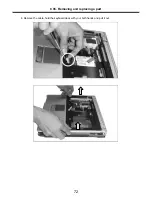
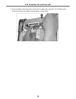
Страница 56: ...55 3 Disconnect the keyboard connector Ch5 Removing and replacing a part ...

Страница 57: ...tainer Remove the following parts in order before replacing this part a Battery Pack 1010 b Keyboard 1030 1 Pull up the retainer and remove the connector using a type screwdriver Ch5 Removing and replacing a part ...

Страница 58: ...lacing this part a Battery Pack 1010 b Keyboard 1030 c Retainer 1040 1 After removing a screw and the connector pull up and remove the fan assembly using a type screwdriver Ch5 Removing and replacing a part 3 M2 0 X L8 8 1SZZBZ4020A 1 Qty Specification FRU No No 1 1 1 ...

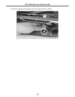
Страница 59: ...58 Ch5 Removing and replacing a part ...

Страница 60: ...driver into the hole located at the rear of ODD and push it out Remove the following parts in order before replacing this part a Battery Pack 1010 b Keyboard 1030 c Retainer 1040 Ch5 Removing and replacing a part 1 1 M2 0 X L5 0 1SZZBZ4014A 1 Qty Specification FRU No No ...

Страница 61: ...t a screwdriver into the back side of ODD and push it out Remove the following parts in order before replacing this part a Battery Pack 1010 b Keyboard 1030 c Retainer 1040 Ch5 Removing and replacing a part 1 1 M2 0 X L5 0 1SZZBZ4014A 1 Qty Specification FRU No No ...

Страница 62: ... 1 Remove two wireless LAN card connector open card knob to take out the card Remove the following parts in order before replacing this part a Battery Pack 1010 b Keyboard 1030 c Retainer 1040 Ch5 Removing and replacing a part ...

Страница 63: ...rewdriver below the modem Pull it up to disassemble Remove the following parts in order before replacing this part a Battery Pack 1010 b Keyboard 1030 c Retainer 1040 Ch5 Removing and replacing a part 1 1 2 M2 0 X L3 5 1SZZBA4017B 1 Qty Specification FRU No No ...

Страница 64: ...crews Remove the following parts in order before replacing this part a Battery Pack 1010 b Keyboard 1030 c Retainer 1040 d Wireless LAN Card 1070 Ch5 Removing and replacing a part 1 2 M2 5 X L8 0 1SZZBA4039B 1 Qty Specification FRU No No 1 ...

Страница 65: ...64 Ch5 Removing and replacing a part 1 2 M2 0 X L5 0 1SZZBZ4014A 1 Qty Specification FRU No No 1 2 Remove two hinge cover screws ...

Страница 66: ...ver with your finger Then more you move the LCD to the back the easier the hinge cover will pull out Remove another hinge cover located on the other side 4 Remove two hinge screws Ch5 Removing and replacing a part 2 M2 5 X L8 0 1SZZBA4039B 1 Qty Specification FRU No No 1 1 ...

Страница 67: ...66 5 Remove the LCD connector located at the upper end of MCD modem You will see a tag designed to make work easier Pull out the tag 4 Remove the LCD cable Ch5 Removing and replacing a part ...

Страница 68: ...67 7 Hold the LCD with your both hands and pull it up to remove Ch5 Removing and replacing a part Note Display Module disassembly in detail 1140 ...

Страница 69: ...lowing parts in order before replacing this part a Battery Pack 1010 b Keyboard 1030 c Retainer 1040 d Fan Assembly 1050 e Wireless LAN Card 1070 f MDC Modem Card 1080 g Display Module 1090 Ch5 Removing and replacing a part 1 M2 0 X L13 0 1SZZBA4067A 2 13 M2 0 X L8 0 1SZZBA4083A 1 Qty Specification FRU No No 1 1 1 1 1 1 1 1 1 1 1 1 1 2 Screw Type 15 ...

Страница 70: ...69 Ch5 Removing and replacing a part 1 M2 0 X L13 0 1SZZBA4067A 2 10 M2 0 X L8 0 1SZZBA4083A 1 Qty Specification FRU No No 1 1 1 1 1 1 1 1 1 1 1 1 1 2 Screw Type 1 1 1 1 1 1 1 1 1 1 2 14 1 Screw Type ...

Страница 71: ...70 2 Open the I O port cover and remove two screws Ch5 Removing and replacing a part 2 M2 0 X L3 5 1SZZBA4017B 1 Qty Specification FRU No No 1 1 ...

Страница 72: ...71 3 Remove 3 screws Ch5 Removing and replacing a part 3 M2 0 X L2 0 1SZZBZ4018B 1 Qty Specification FRU No No 1 1 1 ...

Страница 73: ...72 4 Remove the cable hold the keyboard deck with your both hands and pull it out Ch5 Removing and replacing a part ...

Страница 74: ...73 5 Remove the speaker cable located at the front of key deck that is pulled up Ch5 Removing and replacing a part ...

Страница 75: ...efore replacing this part a Battery Pack 1010 b Keyboard 1030 c Retainer 1040 d Fan Assembly 1050 e Wireless LAN Card 1070 f MDC Modem Card 1080 g Display Module 1090 h Keyboard Deck 1100 Ch5 Removing and replacing a part 2 M2 0 X L5 0 1SZZBZ4014A 1 15 2 M2 0 X L2 5 1SZZBZ3009B 1 14 1 Qty Specification FRU No No 1 1 ...

Страница 76: ...75 2 Remove the PCMCIA board Ch5 Removing and replacing a part 3 Remove the RTC battery connector from Main Board ...

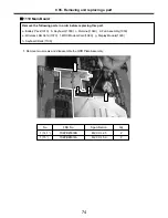
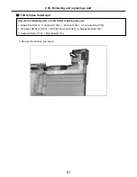
Страница 77: ...76 4 Remove the S Video connector Ch5 Removing and replacing a part 5 Remove the LAN S B connector ...

Страница 78: ...77 6 Remove the power cable Ch5 Removing and replacing a part 7 Remove 4M B screws 1 M2 0 X L3 5 1SZZBA4017B 2 3 M2 0 X L5 0 1SZZBA4014A 1 Qty Specification FRU No No 2 1 1 1 ...

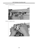
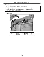
Страница 79: ...78 8 Hold M B with your both hand and pull it up to remove Ch5 Removing and replacing a part ...

Страница 80: ... replacing this part a Battery Pack 1010 b Keyboard 1030 c Retainer 1040 d Fan Assembly 1050 e Wireless LAN Card 1070 f MDC Modem Card 1080 g Display Module 1090 h Keyboard Deck 1100 i Main Board 1110 Ch5 Removing and replacing a part 1 1 M2 0 X L3 5 1SZZBA4017B 1 Qty Specification FRU No No ...

Страница 81: ...80 2 Pull up the battery frame finger plate and remove the battery frame assembly The LAN S B will be removed as well when the battery frame assembly is disassembled Ch5 Removing and replacing a part ...

Страница 82: ...e following parts in order before replacing this part a Battery Pack 1010 b Keyboard 1030 c Retainer 1040 d Fan Assembly 1050 e Wireless LAN Card 1070 f MDC Modem Card 1080 g Display Module 1090 h Keyboard Deck 1100 i Main Board 1110 Ch5 Removing and replacing a part ...

Страница 83: ...ve all 7 screws Remove the following parts in order before replacing this part a Battery Pack 1010 b Keyboard 1030 c Retainer 1040 d Fan Assembly 1050 e Wireless LAN Card 1070 Ch5 Removing and replacing a part 1 1 1 1 2 M2 5 XL5 0 1SZZBA4068A 2 5 M2 5 X L4 0 1SZZBA4044B 1 Qty Specification FRU No No 1 2 2 ...

Страница 84: ... Disassemble the LCD front The front hook located on the middle of LCD upper and lower end Be careful of the direction when removing because it is connected from inside out Ch5 Removing and replacing a part ...

Страница 85: ...84 3 Remove cable connector Remove the cable that is arranged around LCD from LCD frame Ch5 Removing and replacing a part ...

Страница 86: ... 9 screws for 15 model or 8 screws for 14 1 Ch5 Removing and replacing a part 1 1 1 1 2 3 2 2 2 15 1 M2 0 X L3 0 1SZZBA4041A 3 15 4 M2 5 XL4 0 1SZZBA4044B 2 4 M2 0 X L2 5 1SZZBZ3009B 1 Qty Specification FRU No No ...

Страница 87: ...86 5 Press the hook on the both side of LCD with a type screwdriver and remove from the LCD real panel Ch5 Removing and replacing a part ...

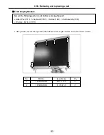
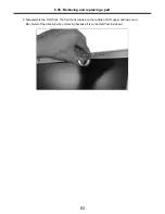
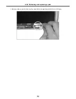
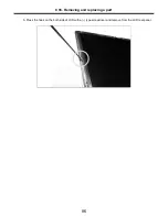
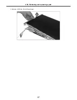
Страница 88: ...87 6 Remove LCD from the LCD rear panel Ch5 Removing and replacing a part ...

Страница 89: ...or refresh model MCKINLEY MG DISPLAY REAR 15 0 FOR MC REFRESH 3110BD0009D MKL14 REAR CASE 15 0 FOR EXPORT 3110BD0009B MKL14 INVERTER DELTA DAC 08B043A 6708BI0083A MKL13 INVERTER ALPS KUBNKM063A 6708BI0082A MKL13 CABLE FPC WIRELESS INDICATOR 15 1 6871BZT17AA MKL12 CABLE ASSY LCD 15 0 6851B76028A MKL11 HINGE ASSY RIGHT 15 0 4775B00034A MKL10 HINGE ASSY LEFT 15 0 4775B00033A MKL09 CUSHION RUBBER LOWE...

Страница 90: ...MSUNG M470L6423EN0 CB3 SODIMM 512MB DDR 333MHZ 0IMMRSS091A MKC01 MEMORY INFINEON HYS64D32020GDL 6 B SODIMM 256MB DDR 333MHZ 0IMMRIH032A MKC01 MEMORY HYNIX HYMD232M646C6 J SODIMM 256MB DDR 333MHZ 0IMMRHY044A MKC01 MEMORY SAMSUNG M470L3224FT0 CB3 SODIMM 256MB DDR 333MHZ 0IMMRSS090A MKC01 For refresh model MCKINLEY US007506 REFRESH MODEL LGE 8 LAYERS REV 0 7 M11 MAINSTEAM MAIN ASSY 6871BF300A1 MKB01 ...

Страница 91: ...MKC08 For refresh model MCKINLEY N SUNREX UKRAINIAN LM REFRESH 14 3823B71004G MKC08 MCKINLEY LG IBM SUNREX K021167 UKRAINIAN 14 1 84 KEY 3823B70004G MKC08 For refresh model MCKINLEY LG IBM SUNREX US SOUTH AFRICA LM REFRESH 14 3823B71004H MKC08 MCKINLEY LG IBM SUNREX K021167 US SOUTH AFRICA 14 1 84 KEY 3823B70004H MKC08 For refresh model MCKINLEY LG IBM SUNREX FARSI LM REFRESH 14 3823B71004F MKC08 ...

Страница 92: ... 86KEY 3823B70008H MKC08 For refresh model MCKINLEY LG IBM OKI FARSI LM REFRESH 15 3823B71008F MKC08 MCKINLEY LG IBM OKI FARSI 15 86 KEY 3823B70008F MKC08 For refresh model MCKINLEY LG IBM OKI HEBREW LM REFRESH 15 3823B71008E MKC08 MCKINLEY LG IBM SUNREX K020346A HEBREW 15 86 KEY 3823B70008E MKC08 For refresh model MCKINLEY LG IBM OKI ARAB LM REFRESH 15 3823B71008D MKC08 MCKINLEY LG IBM OKI ARABIA...

Страница 93: ...U CELERON M 1200MHZ 400MHZ B1 STEPPING SL79S 0IMCRIN150A MKC10 PROCESSOR INTEL RH80535GC0291M 478P UFCPGA PENTIUM M 1700MHZ 600MHZ B1 STEPPING SL6N5 0IMCRIN119A MKC10 PROCESSOR INTEL RH80535GC0251M 478P UFCPGA PENTIUM M 1600MHZ 600MHZ B1 STEPPING SL6FA 0IMCRIN106B MKC10 PROCESSOR INTEL RH80535GC0211M 478P UFCPGA PENTIUM M 1500MHZ 600MHZ B1 STEPPING SL6F9 0IMCRIN105B MKC10 PROCESSOR INTEL RH80535GC...

Страница 94: ...5S VOLEX CCC 1830MM 3PIN CONN BLACK 6410BO21008 MKC13 China SP 506 RVV 3CX0 75MM2 IS 034 I SHENG CCC 1830MM 3P CONN BLACK 6410BO20602 MKC13 China P48F1SAJ30A 060 LONGWELL CCC 1830MM 3P CONN BLACK 6410BO20603 MKC13 Brazil SP 305 H05VV F IS 034 I SHENG INMETRO 1830MM 3PIN CONN BLACK 6410BQ21003 MKC13 Brazil BR10S3 H03VV F VAC5S VOLEX INMETRO 1830MM 3PIN CONN BLACK 6410BQ21002 MKC13 India X LGPC0415 ...

Страница 95: ...FOR MC REFRESH 3111BZ8800C MKD01 For refresh model MCKINLEY N N MCKINLEY KBD DECK TOTAL ASSY 15 0 FOR MC REFRESH 3111BZ8801D MKD01 KBD DECK ASSY 14 1 3111BZ8800A MKD01 For refresh model N N KBD DECK ASSY 15 MCKINLEY KBD DECK W UV COATED KNOB 3111BZ8801B MKD01 KBD DECK ASSY 15 0 3111BZ8801A MKD01 For refresh model MCKINLEY LG IBM N N WIMTEC 2 LAYERS REV 0 4 NETWORK PWR SUB B D ASSY 6871BJ300AB MKS0...

Страница 96: ...7 SCREW D3 8 M2 0 L 2 5 MM TORQUE 2 0 0 2 1SZZBZ3009B MKM23 SCREW D4 5 M2 5 L4 0 MM TORQUE 2 0 0 2 1SZZBA4044B MKM22 SCREW D4 5 M2 5 L5 0 MM TORQUE 2 0 0 2 1SZZBA4068A MKM21 SCREW D2 0 M2 0 L 3 5 MM TORQUE 2 0 0 2 1SZZBA4017B MKM19 THERMAL PAD 11X11 MM ON NORTHBRIDGE 5022BP4010B MKM18 THERMAL PAD 15X25 MM ON ATI 5022BP4010A MKM17 THERMAL PAD 19X19 MM ON FAN 5022BZ4025A MKM16 PLATE CHIPSET COVER AS...

Страница 97: ...036A LENS WIRELESS REAR 14 1 MKL23 3550BM1149B DECORATION COVER 14 1 FOR EXPORT MKL27 3858BZ3020A INSULATOR LED 14 1 MKL28 3110BD0008B REAR CASE 14 1 FOR EXPORT MKL28 3110BD0008D MCKINLEY MG DISPLAY REAR 14 1 FOR MC REFRESH For refresh model MKL29 6871BZT16ZA CABLE FPC WIRELESS INDICATOR 14 1 MKL31 3858BZ4450B MCKINLEY N N N MCKINLEY BADGE FOR EXPORT LG For refresh model ...

Страница 98: ... 1 MKL14 3110BD0009B REAR CASE 15 0 FOR EXPORT MKL14 3110BD0009D MCKINLEY MG DISPLAY REAR 15 0 FOR MC REFRESH For refresh model MKL15 3858BZ3019A INSULATOR INVERTER 14 1 15 0 MKL17 3550BM2093B DECORATION COVER 15 0 FOR EXPORT MKL23 3550BM1149B DECORATION COVER 14 1 FOR EXPORT MKL31 3858BZ4450B MCKINLEY N N N MCKINLEY BADGE FOR EXPORT LG For refresh model ...

Страница 99: ...98 MKM22 MKM22 MKL16 MKM23 MKM23 MKL13 MKL18 MKL06 MKL05 MKL04 MKL20 14 1 MKL02 15 0 MKL09 15 0 MKL24 14 1 MKL26 14 1 MKL11 15 0 MKL10 15 0 MKL25 14 1 MKM23 MKM23 ...

Страница 100: ...15 0 MKL11 6851B76028A CABLE ASSY LCD 15 0 MKL13 6708BI0082A INVERTER ALPS KUBNKM063A MKL13 6708BI0083A INVERTER DELTA DAC 08B043A MKL16 3301BZ0512B ANTENNA WIRELESS RIGHT MKL18 3301BZ0513B ANTENNA WIRELESS LEFT MKL20 6304FBH004A TFT LCD BOE HYDIS HT14X1B 110 14 1 INCH XGA MKL20 6304FLP079A TFT LCD LG PHILIPS LP141X13 C2 14 1 INCH XGA MKL20 6304FLP079B LP141X13 C2K1 LG PHILPS TFT COLOR 14 1 INCH X...

Страница 101: ...100A CASE ASSY FRONT 14 1 MKL30 3850BB3035D MODEL NAME LABEL MCKINLEY 14 1 FOR EXPORT MKL30 3850BB3035E MODEL NAME LABEL MCKINLEY 15 0 FOR EXPORT MKL30 3850BB3035P MCKINLEY N N MODEL NAME LABEL 14 1 MCKINLEY LM40A For refresh model FOR REFRESH EXPORT MKL30 3850BB3035Q MCKINLEY N N MODEL NAME LABEL 15 MCKINLEY LM50A For refresh model FOR REFRESH EXPORT MKM21 1SZZBA4068A SCREW D4 5 M2 5 L5 0 MM TORQ...

Страница 102: ...101 MKM02 14 1 MKB01 MKS02 14 1 MKS03 15 0 MKS04 14 1 MKS01 15 0 MKM01 15 0 MKM03 14 1 MKS06 MKM19 MKM19 MKM19 MKM19 Cardbus MKC05 MKC04 MKM32 MKC12 MKM04 15 0 MKC04 MKM38 Mini PCI MDC Modem ...

Страница 103: ... CASE ASSY 14 1 MKM02 3111BZ9900B GIRAFFE BOTTOM ASSY 14 1 ONLY PCMCIA W PAINT SUB PARTS MKM02 3111BZ9900C MCKINLEY N N MCKINLEY BOTTOM FOR MC REFRESH 14 1 For refresh model MKM03 3210BD2014A FRAME HINGE BATTERY 14 1 MKM04 3210BD1005A FRAME HINGE BATTERY 15 0 MKM19 1SZZBA4017B SCREW D2 0 M2 0 L 3 5 MM TORQUE 2 0 0 2 MKM32 1SZZBZ4014A SCREW D4 3 M2 0 L5 0 MM TORQUE 2 0 0 2 MKM38 4986BZ4117A GASKET ...

Страница 104: ...103 MKH04 MKH02 MKH03 MKM27 MKM27 MKM19 MKS05 MKC02 15 ODD I F MKM12 14 M9 3301BZ9092A M10 3301BZ9092C 15 M9 3301BZ9092D M10 3301BZ9092B MKC07 MKM38 MKM29 MKC10 MKM16 MKM17 MKM18 MKM23 14 MKM32 15 ...

Страница 105: ...Z B1 STEPPING SL6N5 MKC10 0IMCRIN150A RH80535NC009512 LG INTEL 478P UFCPGA TRAY NT CPU CELERON M 1200MHZ 400MHZ B1 STEPPING SL79S MKC10 0IMCRIN132A RH80535NC013512 LG INTEL 478P UFCPGA TRAY NT CPU CELERON M 1300MHZ 400MHZ B1 STEPPING SL6N7 MKC10 0IMCRIN133A RH80535NC017512 LG INTEL 478P UFCPGA TRAY NT CPU CELERON M 1400MHZ 400MHZ B1 STEPPING SL6N6 MKH02 3301B00525A HDD PLATE ASSY MKH03 3110BM3021A...

Страница 106: ...2BP4010A THERMAL PAD 15X25 MM ON ATI MKM18 5022BP4010B THERMAL PAD 11X11 MM ON NORTHBRIDGE MKM19 1SZZBA4017B SCREW D2 0 M2 0 L 3 5 MM TORQUE 2 0 0 2 MKM23 1SZZBZ3009B SCREW D3 8 M2 0 L 2 5 MM TORQUE 2 0 0 2 MKM27 1SZZBA4011F SCREW D5 5 M3 0 L3 5 MM TORQUE 2 0 0 2 MKM29 1SZZBZ4020A SCREW D4 0 M2 0 L8 8 MM TORQUE 1 5 0 2 MKM32 1SZZBZ4014A SCREW D4 3 M2 0 L5 0 MM TORQUE 2 0 0 2 MKM38 4986BZ4117A GASK...

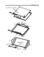
Страница 107: ...MKD01 MKM33 MKM31 ODD MKM32 MKD04 MKM39 MKD03 106 ...

Страница 108: ...Y N N MCKINLEY KBD DECK TOTAL ASSY 14 1 FOR MC REFRESH For refresh model MKD03 6401B10002A SPEAKER ASSY ESTEC A252SX 012K14 0 8W 4PIN 166 5X27MM 8OHM 75DB MKD04 6871BJ340AA MCKINLEY WIMTEC 2 LAYERS REV 0 3 TOUCHPAD 15 0 SUB B D ASSY MKD04 6871BJ330AA MCKINLEY WIMTEC 2 LAYERS REV 0 3 TOUCHPAD 14 1 SUB B D ASSY MKM31 1SZZBZ4018B SCREW D3 8 M2 0 L2 0 MM TORQUE 1 5 0 2 MKM32 1SZZBZ4014A SCREW D4 3 M2 ...

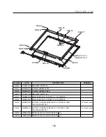
Страница 109: ...108 MKC08 MKM08 MKM32 MKM30 MKM09 MKM10 MKM11 MKM32 MKM06 15 0 MKM07 14 1 MKM30 ...

Страница 110: ...UNREX K021167 PORTUGUESE 14 1 84 KEY MKC08 3823B70004L MCKINLEY LG IBM SUNREX K021167 POLISH 14 1 84KEY MKC08 3823B71004L MCKINLEY LG IBM SUNREX POLISH LM REFRESH 14 For refresh model MKC08 3823B70004M MCKINLEY N SUNREX K021167 FRENCH 14 1 84KEY MKC08 3823B71004M MCKINLEY LG IBM SUNREX FRENCH REFRESH LM 14 For refresh model MKC08 3823B70004N MCKINLEY N SUNREX THAILAND 14 84KEY MKC08 3823B71004N MC...

Страница 111: ...8 3823B71008M MCKINLEY LG IBM OKI FRENCH REFRESH LM 15 For refresh model MKC08 3823B70008N MCKINLEY LG IBM SUNREX THAILAND 15 LM 84KEY MKC08 3823B71008N MCKINLEY N OKI THAILAND LM REFRESH 15 For refresh model MKC08 3823B70008P MCKINLEY LG IBM OKI TAIWAN 15 LM 86KEY MKC08 3823B71008P MCKINLEY N OKI TAIWAN LM REFRESH 15 For refresh model MKC08 3823B71008Q MCKINLEY N OKI HUNGARY LM REFRESH 15 For ref...

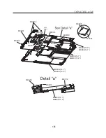
Страница 112: ...111 MKC06 MKM05 MKM30 MKM28 MKM33 MKM33 MKM33 MKM34 MKM33 MKM19 MKM30 MKC01 MKC11 MKC13 ...

Страница 113: ...K21007 SP 502B H05VV F IS 034 I SHENG SAA 1830MM 3PIN CONN BLACK Australia MKC13 6410BK21006 AU10S3 H03VV F VAC5S VOLEX SAA 1830MM 3PIN CONN BLACK Australia MKC13 6410BX21601 SP 022 IS 034 H05VV F3G I SHENG GOST 1800MM 3P CONN BLACK Russia MKC13 6410BX21602 PF8B1CIJ10A 060 LONGWELL GOST 1830MM 3PIN CONN BLACK Russia MKC13 6410BD21602 PF8B1CIJ10A 060 LONGWELL CEU 1830MM 3P CONN BLACK Spain MKC13 64...

Страница 114: ...KM19 1SZZBA4017B SCREW D2 0 M2 0 L 3 5 MM TORQUE 2 0 0 2 MKM28 1SZZBA4067A SCREW D4 0 M2 0 L13 0 MM TORQUE 2 0 0 2 MKM30 1SZZBA4039B SCREW D4 5 M2 5 L8 0 MM TORQUE 3 0 0 2 MKM33 1SZZBA4083A SCREW D3 8 M2 0 L8 0 MM TORQUE 2 0 0 2 MKM34 1SZZBA4085A SCREW D5 5 M3 0 L6 0 MM TORQUE 2 0 0 2 ...

Отзывы: