


18
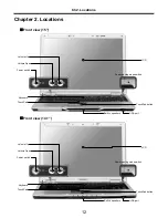
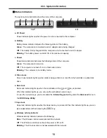
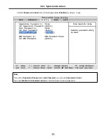
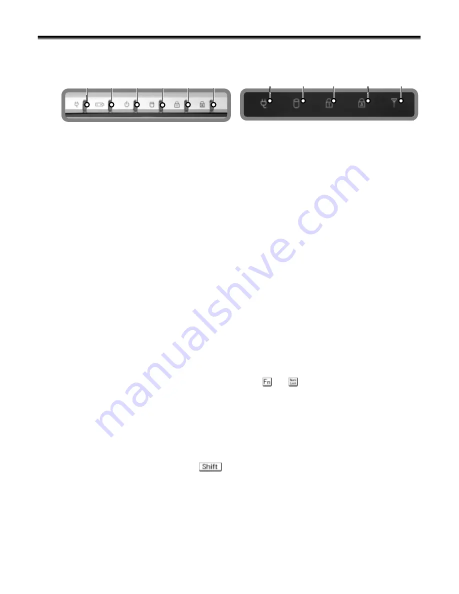
Status indicators
· The system status indicators show the status of the computer.
d. Drive in use
Drive in use indicator lights up when data is being written to or read from the hard-disk or optical disk
drive.
f. Caps Lock
Caps lock indicator lights up when the Caps lock key is pressed. When this indicator lights up, you can
type capital letters without pressing the key.
Ch3. System information
d
e
f
g
a
d
b
e
f
c
a
a. AC Power
Power indicator lights up when the power cord is connected to the computer.
e. Num Lock
Num Lock indicator lights up when the combination of the
and key is pressed.
When this indicator lights up, you can use the embedded numeric keys.
(To use the numeric keys, you must enable the
Internal Keypad
setting under the
Advanced
menu in
the
BIOS Setup Utility
)
g. Wireless activity indicator
Wireless activity indicator indicates the following.
Blue
: The Wireless client is associated with the network.
Off
: The Wireless card does not have the power or RF is off.
Blinking
: The Wireless client is not associated with the network.
c. Power
Power status indicator indicates the following status of the computer.
Green
: The computer is turned on.
Off
: The computer is turned off or is in hibernation mode.
Blinking
: The computer is in standby mode.
b. Battery
Battery status indicator indicates the following status of the battery.
Green
: The computer is connected to an AC adapter and is being charged.
Off
: The battery if fully charged OR the computer is not connected to an AC adapter.
Blinking
: The battery power is under 10% of its maximum capacity.
14.1”
15”
Содержание LM40
Страница 1: ...0 Service Manual LM40 50 LG Electronics ...
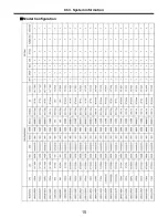
Страница 16: ...15 Model Configuration Ch3 System information ...
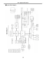
Страница 17: ...16 System Block Diagram Ch3 System information ...
Страница 56: ...55 3 Disconnect the keyboard connector Ch5 Removing and replacing a part ...
Страница 59: ...58 Ch5 Removing and replacing a part ...
Страница 77: ...76 4 Remove the S Video connector Ch5 Removing and replacing a part 5 Remove the LAN S B connector ...
Страница 79: ...78 8 Hold M B with your both hand and pull it up to remove Ch5 Removing and replacing a part ...
Страница 88: ...87 6 Remove LCD from the LCD rear panel Ch5 Removing and replacing a part ...
Страница 107: ...MKD01 MKM33 MKM31 ODD MKM32 MKD04 MKM39 MKD03 106 ...
Страница 109: ...108 MKC08 MKM08 MKM32 MKM30 MKM09 MKM10 MKM11 MKM32 MKM06 15 0 MKM07 14 1 MKM30 ...
Страница 112: ...111 MKC06 MKM05 MKM30 MKM28 MKM33 MKM33 MKM33 MKM34 MKM33 MKM19 MKM30 MKC01 MKC11 MKC13 ...


