3
❏
Occasionally CD-R and CD-RW discs written by a CD-R/RW drive cannot be read by other CD drives*.
These unreadable discs may need to be read using the CD-R/RW drive they were created with
*
The disc written using the CD-R/RW drive might not be readable by CD-ROMs other than Multi-read
compatible (UDF compatible) CD-ROMs
Multiread compatible (UDF compatible) CD-ROMs are:
1. CD-ROMs that can read low reflectance.
2. CD-ROMs that support Packet Write.
❏
Please note:
Certain software (i.e. particularly those including Video playback) may require a
considerably increased specification PC to give acceptable results. While this Super Multi DVD
Drive can read DVD-video discs, decoding them to display on your pc’s monitor requires separate
MPEG decoding that is done by separate hardware (either an MPEG decoder card or MPEG
decoding done by your video card), or separate software that you install to do MPEG decoding.
For further details, refer to the documentation that comes with MPEG software.
Software
Install the supplied CD/DVD Recording, Authoring & DVD-RAM Driver Software before using this unit.
* Please uninstall any previous CD burning software you may have loaded on your PC in order to pre-
vent possible compatibility issues. Once you have installed the supplied software, you may (if you wish)
begin to reinstall previous software, taking note for errors.
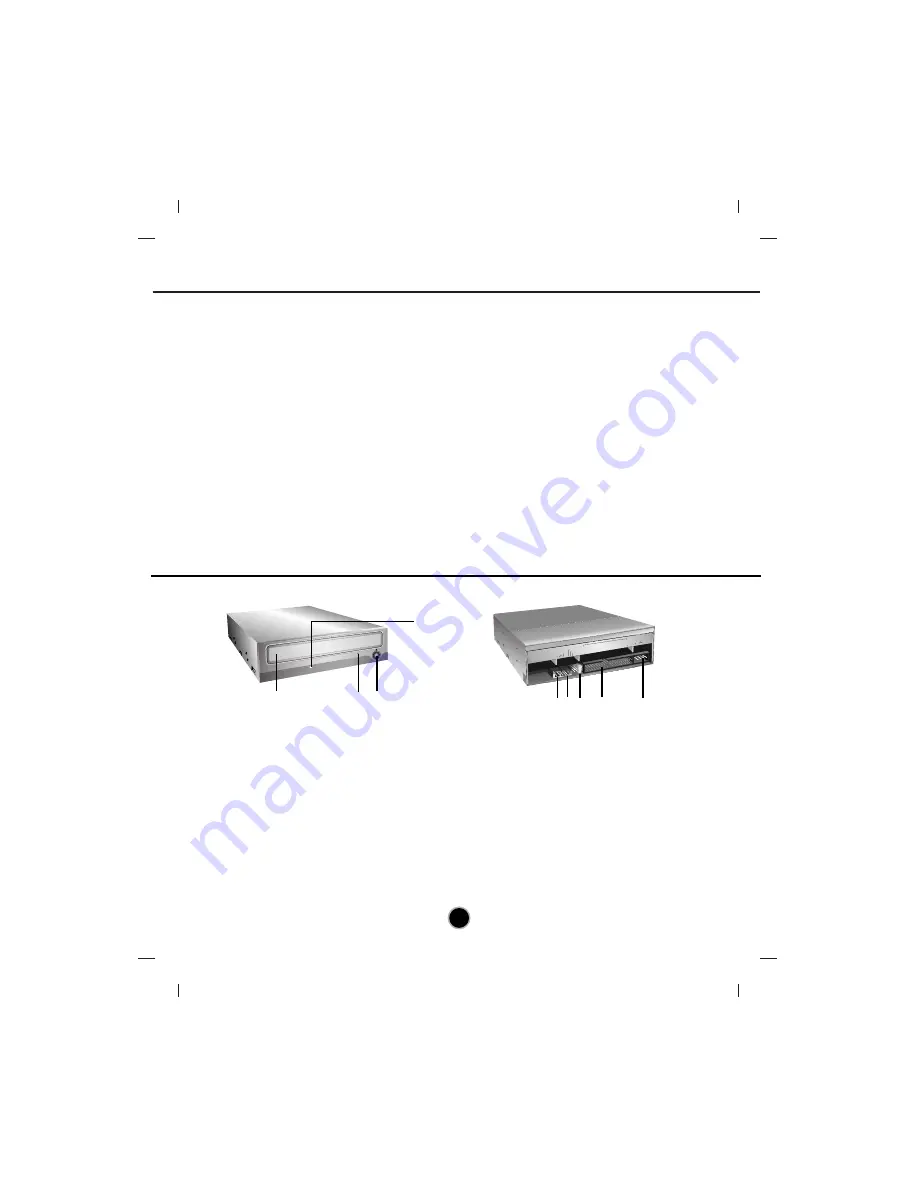
Front Panel
Location and Function of Controls
1. Disc Tray
2. Emergency Eject Hole
3. Stop/Eject Button
4. Drive activity indicators
The LED used to indicate the operation of
Super Multi DVD Drive.
Read:
The green color is displayed during disc reading session.
Write:
The green color is flashed during disc writing
sessions.(CD-R/RW, DVD-R/RW)
The green color is displayed during disc
writing session. (DVD-RAM, DVD+R/RW)
1. Digital Audio Output Connector
This connector is not supported.
2. Analog Audio Output Connector
3. Jumper Connector
This jumper determines whether the drive is configured
as a master or slave. Changing the master-slave
configuration takes effect after power-on reset.
4. IDE Interface Connector
Connect to the IDE (Integrated Device Electronics)
Interface using a 40-pin flat IDE cable.
NOTE :
Do not connect or disconnect the cable when
the power is on, as this could cause a short circuit
and damage the system. Always turn the power OFF
when connecting or disconnecting this cable.
5. Power Connector
Rear Panel
4
1
3
2
AUDIO O
UT
SELECT
IDE INT
ERFAC
E CON
NECTO
R
INPUT
DC
39
40
1
2
5V GN
D 12V
R GND
L
C.SEL
SLAVE
MASTE
R
1 2 3 4
5


