background image

4

Before installing the drive, please note the following points.

You will need the following:
•  A screw driver of a suitable size to fit the securing screws for the drive unit.
•  The manual for the computer, so you can find the mounting positions for the IDE 

controller cable.

Turn off all peripheral appliances of the computer and the computer itself, and disconnect
their power cords from the wall sockets.

Discharge any static electricity on your person by touching the computer covers, etc.

Removing the Computer Cover

Make sure all peripheral devices of the computer and the computer itself are turned off, and then
remove the cover. Refer to the manual for the computer for details about removing the cover.

NOTE 

: There may be sharp edges inside the computer so take care to avoid injury.

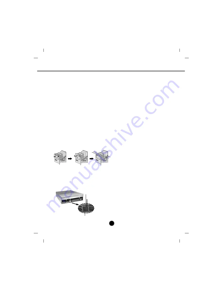
Mounting the Drive

1. Remove the 5

1

/

4

″ 

drive bay panel from the computer. Refer to the manual for the computer for

details.

2. Insert the drive unit into the bay. Do not apply excessive pressure to the cables inside the

computer.

3. Secure the drive with the screws provided. If there is not enough space behind the drive,

connect the IDE and other cables before securing the drive.

NOTE

: This is a general installation guide. If your 

PC hardware appears different, please consult your

hardware manual for installing peripheral devices.

Jumper Setup

Before installation, set the jumper connector on the rear panel.
The drive can be connected as the Master or Slave on an EIDE (ATAPI) interface. When several
(up to four) EIDE devices are connected, each must be set in a unique way. Specific knowledge
of hardware and software is necessary to install the drive.

Installing the Drive

READ

READ

WRIT

E

READ

READ

WRIT

E

NOTE

: If two peripheral devices with the same settings

are both connected to the Primary or to the Secondary
EIDE bus, the host computer may fail to run or may
malfunction. Careful attention is necessary.

AUDIO O

UT

SELECT

IDE  INTERFACE  CONNECTOR

INPUT

DC

39
40

1
2

5V GN

D 12V

R GND

 L

C.SEL

SLAVE

MASTE

R

MA: Master

SL: Slave

CS: Cable Select (CSEL)

Содержание GSA-4081B

Страница 1: ...GSA 4081B Super Multi DVD Drive English Deutsch Français Italiano Español Português ...

Страница 2: ...ection against harmful interference in a residential installation This equipment generates uses and can radiate radio frequency energy and if not installed and used in accordance with the instructions may cause harmful interference to radio communications However there is no guarantee that interference will not occur in a particular installation If this equipment does cause harmful interference to...

Страница 3: ...zed by the same Compact Disc ReWritable Ultra Speed logo on the disc label or packaging material Attempting to write to Ultra Speed CD RW media using CD RW drives NOT bearing the logo Compact Disc ReWritable Ultra Speed may result in data loss Recordable ReWritable ReWritable High Speed ReWritable Ultra Speed This product is manufactured to comply with the radio interference requirements of EEC DI...

Страница 4: ...max Writing DVD RW 4X max Writing DVD RW 32X max Reading CD ROM CD R 24X max Reading CD RW 12X max Reading DVD ROM single 8X max Reading DVD ROM dual 8X max Reading DVD R RW DVD R RW DVD VIDEO 3X Reading DVD RAM Writing speed depends highly on capabilities of discs As a result for highspeed rewrite it supports max 8x or max 12x speed not 10x speed CD RW Writing Low speed 4X High speed 8X 10X Ultra...

Страница 5: ...e please consult the dealer where the drive was purchased Don t interrupt the electric power while the drive is operating When connecting two IDE devices to the Primary or Secondary connectors make sure that the two devices are not configured as both Master or both Slave If they are both set the same Windows may fail to run or recognize the drives The total length of the IDE cable should be no mor...

Страница 6: ... may have loaded on your PC in order to pre vent possible compatibility issues Once you have installed the supplied software you may if you wish begin to reinstall previous software taking note for errors Front Panel Location and Function of Controls 1 Disc Tray 2 Emergency Eject Hole 3 Stop Eject Button 4 Drive activity indicators The LED used to indicate the operation of Super Multi DVD Drive Re...

Страница 7: ...t the drive unit into the bay Do not apply excessive pressure to the cables inside the computer 3 Secure the drive with the screws provided If there is not enough space behind the drive connect the IDE and other cables before securing the drive NOTE This is a general installation guide If your PC hardware appears different please consult your hardware manual for installing peripheral devices Jumpe...

Страница 8: ...jumper can be left as supplied from the factory NOTE A hard disk is normally installed as the Primary Master on the EIDE ATAPI interface Other EIDE peripheral devices such as hard drives and Super Multi DVD Drives are then set differently Name Function Drive set as Master Drive set as Slave Drive mode set by CSEL on the host IDE interface MA Master SL Slave CS Cable Select C S S L M A Primary conn...

Страница 9: ...Jumper set to Slave Master drive Booting hard disk OR DIGITAL ANALOG INTERFACE POWER D R C S M S L A G L G 39 1 5 12 GND 40 2 AUDIO AUDIO Primary connector Secondary connector Master drive Other IDE drive Slave drive Super Multi DVD Drive Jumper set to Slave DIGITAL ANALOG INTERFACE POWER D R C S M S L A G L G 39 1 5 12 GND 40 2 AUDIO AUDIO DIGITAL ANALOG INTERFACE POWER D R C S M S L A G L G 39 1...

Страница 10: ...nel System Device Manager CD ROM Windows 2000 XP Control Panel System Hardware Device Manager DVD CD ROM drives 32 bit is displayed in Control Panel System Performance If the drive is not recognized by your computer please check the following items If an indicator is displayed on the IDE controller in Control Panel System Device Manager Hard Disk Controller you will need to contact your PC s manuf...

Страница 11: ...the CD to be ejected manually if this becomes necessary such as failure of the drive or a power outage NOTE Don t use this feature except in an emergency 1 Turn the power to OFF 2 Poke a fine tipped object such as a straightened heavy duty paper clip into the small hole above the eject button The front door will pop open and the disk tray will come partway out 3 Pull the front door to open it all ...

Страница 12: ... disc Is there enough free space on the CD R RW DVD R RW DVD R RW and DVD RAM disc Does writing fail even using the simulation test Is the disc loaded in the drive with the read write surface facing the right direction 7 label up Is the drive installed in the correct orientation Was the drive or disc moved from a low temperature environment to a high temperature environment There is a possibility ...

Страница 13: ...es s PIO Mode 4 MULTI DMA Mode 2 33 3 Mbytes s Ultra DMA Mode 2 CD ROM 135msec Typical DVD ROM 155msec Typical DVD RAM 185msec Typical 2 Mbytes 100000 Power On Hours Duty Cycle 10 0 7 Vrms at 47 kohm Typical Temperature 5 C to 45 C Humidity 15 to 85 R H Temperature 30 C to 60 C Humidity 10 to 90 R H 5 75 x1 63 x7 27 146 x 41 3 x 184 7 mm without front bezel Less than 2 1lbs 0 94Kg DC 5V DC 12V Ite...

Страница 14: ...y from heat sources Excessive vibration or a sudden jolt to the drive during operation may cause a malfunction Avoid exposing the drive to sudden changes in temperature as it may cause condensation to collect inside the drive Copyright 2003 LG Electronics U S A Inc 1000 Sylvan Ave Englewood Cliffs NJ 07632 U S A or http www lgeus com LG Electronics Canada Inc 550 MATHESON Blvd East Mississauga Ont...

Отзывы: