4
E. Notice of Radiated Emissions
This model complies with rules regarding radiation and radio frequency emission as defined by local
regulatory agencies. In accordance with these agencies, you may be required to provide information
such as the following to the end user.
F. Pictures
The pictures in this manual are for illustrative purposes only; your actual hardware may look slightly
different.
G. Interference and Attenuation
Phone may interfere with sensitive laboratory equipment, medical equipment, etc. Interference from
unsuppressed engines or electric motors may cause problems.
H. Electrostatic Sensitive Devices
ATTENTION
Boards, which contain Electrostatic Sensitive Devices(ESD),are indicated
by the sign .
Following information is ESD handing:
.
Service personnel should ground themselves by using a wrist strap when exchange system boards.
.
When repairs are made to a system board , they should spread the floor with anti-static mat which is
also grounded .
.
Use a suitable, grounded soldering iron .
.
Keep sensitive parts in these protective packages until these are used.
.
When returning system boards or parts like EEPROM to the factory, use the protective packages as
described.
Содержание GB130kf750
Страница 1: ...1 GB130 GB130 GB130 GB130 Service Manual Service Manual Service Manual Service Manual LG Electronics ...
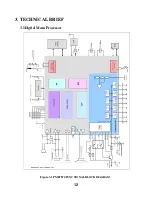
Страница 12: ...12 3 TECHNICAL BRIEF 3 1Digital Main Processor Figure 3 1 PMB7890 FUNCTIONAL BLOCK DIAGRAM ...
Страница 28: ...28 ...
Страница 29: ...29 Pin Description ...
Страница 35: ...35 Circuit Diagram TP1 TP6 TP2 TP4 TP 3 TP5 ...
Страница 36: ...36 Checking Flow ...
Страница 37: ...37 4 2 SIM Card Trouble Test Point Circuit Diagram ...
Страница 38: ...38 Checking Flow ...
Страница 39: ...39 4 3 Vibrator Trouble Test Point Circuit Diagram ...
Страница 40: ...40 Checking Flow NG ...
Страница 41: ...41 4 4 Keypad Trouble Test Point ...
Страница 42: ...42 Circuit Diagram ...
Страница 43: ...43 ...
Страница 44: ...44 Checking Flow ...
Страница 45: ...45 4 5 RTC Trouble Test Point Circuit Diagram ...
Страница 46: ...46 Checking Flow ...
Страница 47: ...47 4 6 Key Backlight Trouble 4 6 1 Main Key Board LED ...
Страница 48: ...48 Circuit Diagram Checking Flow ...
Страница 49: ...49 4 6 2 Upper Key Board LED Circuit Diagram TP1 ...
Страница 50: ...50 Checking Flow ...
Страница 51: ...51 4 7 LCM Backlight Trouble Test Point Circuit Diagram ...
Страница 52: ...52 Checking Flow ...
Страница 53: ...53 4 8 LCM Trouble Test Point Circuit Diagram ...
Страница 54: ...54 Checking Flow ...
Страница 55: ...55 4 9 Microphone Trouble Test Point Circuit Diagram TP1 ...
Страница 56: ...56 Checking Flow ...
Страница 57: ...57 4 10 Receiver Trouble Test Point ...
Страница 58: ...58 Circuit Diagram ...
Страница 59: ...59 Checking Flow ...
Страница 60: ...60 4 11Speaker Trouble Test Point ...
Страница 61: ...61 Circuit Diagram ...
Страница 62: ...62 Checking Flow ...
Страница 63: ...63 4 12 Headphone Trouble Test Point Circuit Diagram ...
Страница 64: ...64 ...
Страница 65: ...65 Checking Flow ...
Страница 66: ...66 ...
Страница 67: ...67 4 13 Charging Trouble Test Point Circuit Diagram TP1 TP4 TP3 TP5 TP2 ...
Страница 68: ...68 Checking Flow ...
Страница 69: ...69 4 14 FM Radio Trouble Test Point ...
Страница 70: ...70 Circuit Diagram ...
Страница 71: ...71 Checking Flow ...
Страница 72: ...72 ...
Страница 74: ...74 RF Trouble TEST POINT ...
Страница 76: ...76 ...
Страница 77: ...77 RX Trouble TEST POINT ...
Страница 78: ...78 CIRCUIT TP5 TP6 TP3 TP4 TP1 TP2 ...
Страница 79: ...79 CHECKING FLOW ...
Страница 80: ...80 TEST POINT CIRCUIT TP1 TP2 TP5 TP6 TP3 TP4 TP2 TP1 ...
Страница 81: ...81 WAVE FORM CHECKING FLOW Replace X301 ...
Страница 82: ...82 TX Trouble TEST POINT ...
Страница 83: ...83 CIRCUIT WAVE FORM TP5 TP6 TP3 TP4 TP2 TP1 ...
Страница 84: ...84 TEST POINT ...
Страница 85: ...85 CHECKING FLOW ...
Страница 86: ...86 Signal configuration CHECKING FLOW ...
Страница 87: ...87 TROUBLE SHOOTING TEST POINT CIRCUIT TP5 TP6 TP3 TP4 TP1 TP2 ...
Страница 88: ...88 WAVE FORM ...
Страница 89: ...89 CHECKING FLOW ...
Страница 90: ...90 5 DOWNLOAD 5 1 Download Setup ...
Страница 94: ...94 It will present a shortcut in the desktop after installing finish This is DWForService download software ...
Страница 99: ...99 2 Downloading Download program will according to software download Every software will display in List ...
Страница 100: ...100 3 DownLoad Fail If download fail that it will show red and display progress in log window ...
Страница 101: ...101 Fig 2 DownLoad success DownLoad Pass will display green color ...
Страница 102: ...102 6 BLOCK DIAGRAM ...
Страница 103: ...103 7 CIRCUIT DIAGRMA ...
Страница 104: ...104 ...
Страница 105: ...105 ...
Страница 106: ...106 ...
Страница 107: ...107 ...
Страница 108: ...108 ...
Страница 109: ...109 ...
Страница 110: ...110 ...
Страница 111: ...111 ...
Страница 112: ...112 8 BGA IC PIN Check 8 1 BGA PIN Check of MCU PMB7890 BGA use BGA non use ...
Страница 113: ...113 8 2 BGA PIN Check of Memory S71GL064NA0BFW0Z0 BGA use BGA non use ...
Страница 129: ...129 11 2 4 Set up Double click the Arima icon will show set up window Fig 16 Double click ARIMA icon window ...
Страница 137: ...137 13 EXPLODED VIEW REPLACEMENT PART LIST 13 1 EXPLODED VIEW ...
Страница 138: ...138 Ass y exploded view ...


