


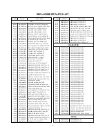


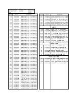

- 25 -
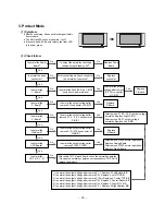
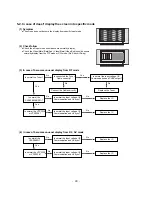
3. Protect Mode
(1) Symptom
Ø
After once shining, it does not discharge minutely
from module
Ø
The Rely falls(The sound is audible “click”)
Ø
It is converted with the color where the front LED
is red from green.
(2) Check follow
Is normal the Power
Board?
Replace Power
Board.
Is output the normality Low/High
voltage except Stand-by 5V?
Yes
No
No
Is normal the each
connector?
Replace
connector.
Replace
Y-Board.
After connecting well each connector,
the normality it operates?
Yes
No
No
Is normal the
Ctrl Board?
Replace
X-Board.
Is normal the output voltage after
remove P101~P106 connector of
Ctrl-B/D?
Yes
No
Yes
Is normal the
Y- Board?
Is normal the output
voltage after remove
(P3, P4) connector
of Y-B/D?
Is normal the Fuse(FS2) on Y-B/D?
(in case of open is replace)
Yes
No
Yes
Yes
Replace
Z-Board.
Is normal the
Z- Board?
Is normal the output voltage after
remove P12 connector of Z-B/D?
Yes
No
Is normal the
X- Board?
Is normal the output voltage after
remove P1, 2, 3, 4, 5 connector of
X-B/D?
After remove P1, P2, P3, P4 output voltage
normality: Replace Right X-B/D
After remove P6, P7 output voltage
normality: Replace Left X-B/D
Yes
No
Yes
Is normal the
VSC Board?
Is normal the output voltage after
remove P1000, P1200?
After crisis COF of each board, check the normality operates.
If in case the normality operates, correspondence COF Fail is
replace the module.
1) Is normal the output Voltage after remove P1 -> Replace X Left-Bottom B/D
2) Is normal the output Voltage after remove P5-> Replace X Left-TOP B/D
3) Is normal the output Voltage after remove P100-> Replace X Center-TOP B/D
4) Is normal the output Voltage after remove P2-> Replace X Center-Bottom B/D
5) Is normal the output Voltage after remove P4-> Replace X Right-TOP B/D
6) Is normal the output Voltage after remove P3 -> Replace X Right-Bottom B/D
After remove P1000 normal operation:
Replace Analog Board
After remove P1200 normal operation:
Replace Digital Board
Yes
No
Is normal the
COF of X, Y, Z?
No
Yes
Yes
Содержание DT-42PY10X
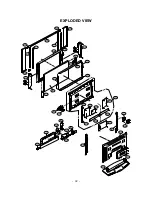
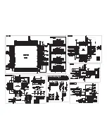
Страница 21: ... 21 1 4 DT 60PY10 Power Board Structure 1 2 3 AC IN ...
Страница 22: ... 22 1 2 3 PFC ...
Страница 23: ... 23 1 2 3 DC DC ...
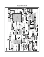
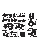
Страница 31: ... 31 BLOCK DIAGRAM BLOCK DIAGRAM ...
Страница 39: ......
Страница 40: ......
Страница 41: ......
Страница 43: ...Dec 2004 Printed in Korea P NO 3828VD0193A ...