[
[
. RS-232C Command
(Automatic Adjustment)
7-3. Adjustment of White Balance(manual)
O
Operate the Zero-calibration of the CA-100, then attach
sensor to PDP module surface when you adjust.
O
Manual adjustment is also possible by the following sequence.
(1) Enter ‘3.White-Pattern’ by pressing ADJ KEY on the
Service Remote Control.
(2) Select "Test Pattern White" using Vol +/- Key and HEAT
RUN at least 15 minutes by pressing the ENTER Key.
(3) Receive the AV 50Hz, Full size, 216 Gray window pattern
signal from AV Pattern Generator.
Input mode : DT-42PY10X : AV2
DT-50PY10 : AV1
DT-60PY10 : AV1
(4) Select the Screen Adjustment as ‘Dynamic’.
(5) After attaching sensor to center of screen, select ‘2. White-
Balance’ of ‘Ez - Adjust’ by pressing the ADJ KEY on the
Service R/C. Then enter adjustment mode by pressing the
Right KEY (
G
) .
(6) Adjust the High Light using R Gain/B Gain.
(7) Adjust using /- KEY.(G Gain: 127)
DT-42PY10X : R Offset : 50/ B Offset : 48/ B Offset: 50
DT-50PY10 : R Offset : 52/ B Offset : 45/ B Offset: 60
DT-60PY10 : R Offset : 55/ B Offset : 50/ B Offset: 55
X; 0.290±0.003
Y; 0.290±0.003
Color temperature: 9,000°K±500°K
(7) After adjustment is complete, move to Ez - Adjust screen
by pressing the ENTER(
Y
) KEY. Then exit the adjustment
mode by press ADJ KEY.
R Gain
G Gain
B Gain
R Cut
G Cut
B Cut
00
00
00
00
00
00
ff
ff
ff
7f
7f
7f
ja 00 XX
jb 00 XX
jc 00 XX
lj 00 XX
lk 00 XX
ll 00 XX
7f
7f(Fix.)
7f
3f(Fix.)
3f
3f
RS-232C Command
[CMD ID DATA]
MIN
CENTER
(DEFAULT)
MAX
- 16 -
Содержание DT-42PY10X
Страница 21: ... 21 1 4 DT 60PY10 Power Board Structure 1 2 3 AC IN ...
Страница 22: ... 22 1 2 3 PFC ...
Страница 23: ... 23 1 2 3 DC DC ...
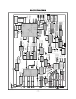
Страница 31: ... 31 BLOCK DIAGRAM BLOCK DIAGRAM ...
Страница 39: ......
Страница 40: ......
Страница 41: ......
Страница 43: ...Dec 2004 Printed in Korea P NO 3828VD0193A ...


