Due to our policy of continuous product innovation, some specifications may change without notification.
©LG Electronics U.S.A., Inc., Englewood Cliffs, NJ. All rights reserved. “LG” is a registered trademark of LG Corp.
26
Braze Procedure
WARNING
Do not braze in an enclosed location.
Do not allow the
refrigerant to leak during brazing. Always test for gas leaks
before and after brazing.
•
If the refrigerant combusts, it generates a toxic gas the will
cause physical injury or death.
It is imperative to keep the piping system free of contaminants
and debris such as copper burrs, slag, or carbon dust during
installation
.
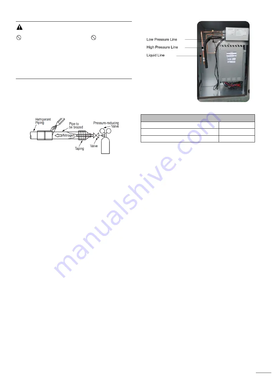
Before brazing the refrigerant piping, perform a nitrogen
replacement procedure or charge nitrogen into the
refrigerant piping during brazing, then connect the unit to
the DOAS unit (Figure 9).
Figure 9: Refrigerant Pipe Brazing
1. All joints are brazed in the field. Multi V refrigeration
system components contain very small capillary
tubes, small orifices, electronic expansion valves, oil
separators, and heat exchangers that can easily
become blocked. Proper system operation depends
on the installer using best practices and utmost care
while assembling the piping system.
2. Store pipe stock in a dry place; keep stored pipe
capped and clean.
3. Blow clean all pipe sections with dry nitrogen prior to
assembly.
4. Use adapters to assemble different sizes of pipe.
5. Always use a non-oxidizing material for brazing. Do
not use flux, soft solder, or anti-oxidant agents. If the
proper material is not used, oxidized film will
accumulate and clog or damage the compressors.
Flux can harm the copper piping or refrigerant oil.
6. Use a tubing cutter, do not use a saw to cut pipe. De-
bur and clean all cuts before assembly.
7. Brazing joints:
•
Use a dry nitrogen purge operating at a minimum
pressure of three (3) psig and maintain a steady
flow.
•
Use a 15% silver phosphorous copper brazing
alloy to avoid overheating and produce good flow.
•
Protect isolation valves, electronic expansion
valves, and other heat-sensitive control
components from excessive heat with a wet rag or
heat barrier spray.
Figure 10: Cabinet Pipe connections
Table 2: Pipe Sizing
DOAS Piping
Liquid OD inch (mm)
1/2 (12.7)
Low Pressure Vapor OD inch (mm)
1-1/8 (28.58)
High Pressure Vapor OD inch (mm)
3/4 (19.05)


