background image

Installation

The Other Types of Video

Cards with BNC

Connectors

HD

: Horizontal Drive

VD

: Vertical Drive

COMP

: Composite 

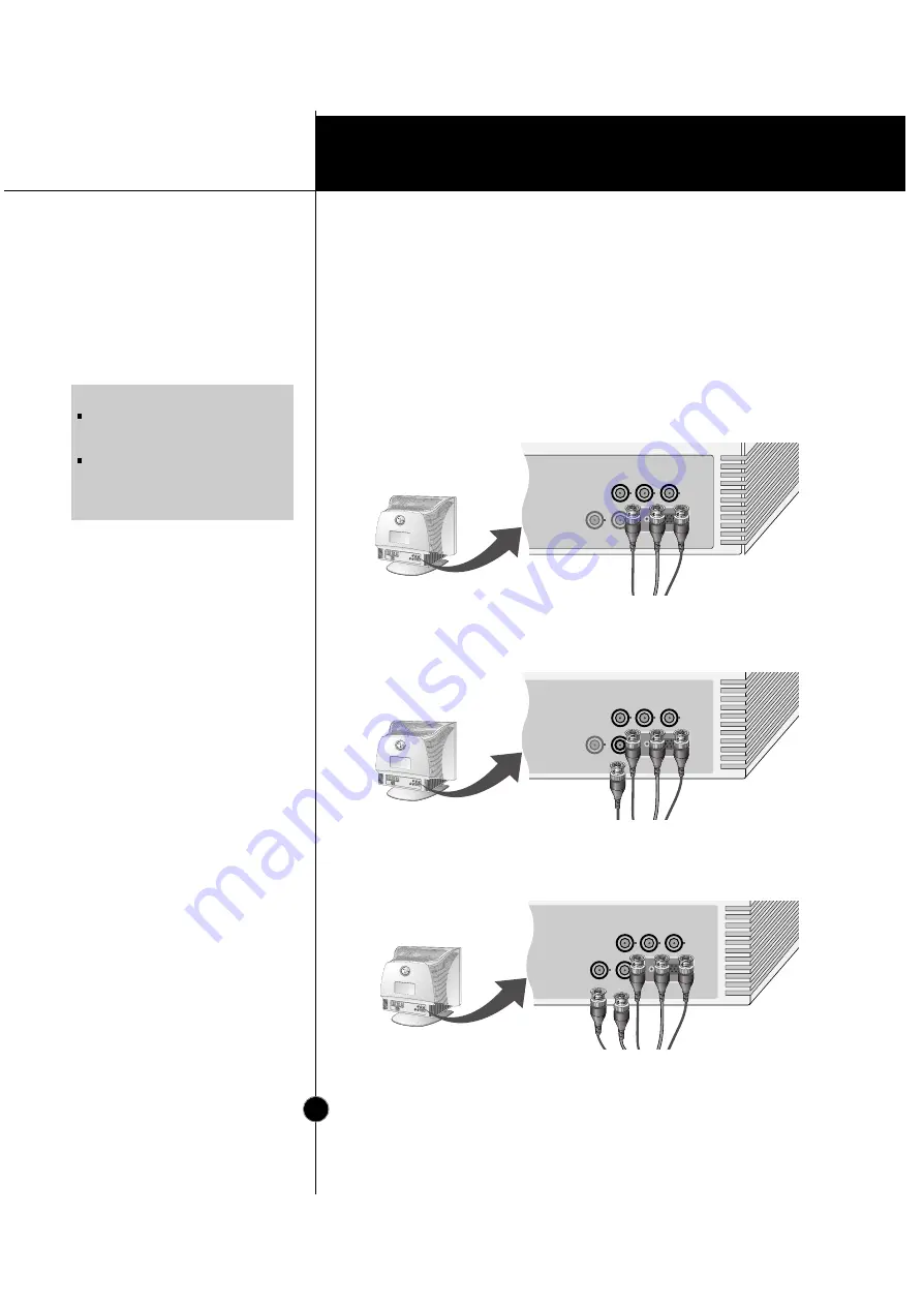
Connecting the Monitor

Notes on using the BNC connectors with other types of video cards.
Follow the example that fits your needs.

1.

In case of composite sync on green video signal(Sync On Green):

Connect R,G and B video signals to BNC receptacles on the back of
the monitor, respectively. 

2.

In case of external composite sync signal:

Connect R, G and B video signals and Composite sync signal to BNC
receptacles on rear panel, respectively. 

3.

In case of separate horizontal and vertical sync signals:

Connect R, G and B video signals and horizontal and vertical sync
signals to BNC receptacles on rear panel respectively.

NOTE

This package does not have BNC
Connectors but you can purchase it at
your local computer store. 
This monitor will not support the DDC
function, if you are using the 5 BNC
connectors with other types of video
cards.

R

G

B

VD

COMP.

   HD

D-SUB


R

G

B

   VD

COMP.

   HD

D-SUB


B

G

R


VD

COMP.


   HD

Blue

Green

Red

Blue

Gray

Green

Red

Blue

Gray

Black

Green

Red

A6

Содержание 915FT

Страница 1: ...al Serial Bus Location and Function of Controls Control Panel Function On Screen Display OSD Control Adjustment On Screen Display OSD Selection and Adjustment Energy Saving Design Low Radiation Compliance MPR II and DDC Display Data Channel Video Memory Modes Troubleshooting Service Specifications A1 A10 A7 A4 A2 A11 A13 A12 A17 A19 A20 A21 A22 A18 ENGLISH i ...

Страница 2: ...patibility makes it possible to upgrade video cards or software without purchasing a new monitor Digitally controlled auto scanning is done with the micro processor for horizontal scan frequencies between 30 and 107kHz and vertical scan frequencies between 50 200Hz The microprocessor based intelligence allows the monitor to operate in each frequency mode with the precision of a fixed frequency mon...

Страница 3: ...al or listed on the monitor If you are not sure what type of power supply you have in your home consult with your dealer Overloaded AC outlets and extension cords are dangerous So are frayed power cords and broken plugs They may result in a shock or fire hazard Call your service technician for replacement Do not Open the Monitor There are no user serviceable components inside There are Dangerous H...

Страница 4: ...ntilation openings in the cabinet to allow the release of heat generated during operation If these openings are blocked built up heat can cause failures which may result in a fire hazard Therefore NEVER Block the bottom ventilation slots by placing the monitor on a bed sofa rug etc Place the monitor in a built in enclosure unless proper ventilation is provided Cover the openings with cloth or othe...

Страница 5: ...itor and PC 2 Connect the 15 pin VGA connector of the supplied signal cable to the output VGA video connector on the PC and the matching input connector on the rear of the monitor The connectors will mate only one way If you cannot attach the cable easily turn the connector upside down and try again When mated tighten the thumbscrews to secure the connection 3 Power ON the PC then the monitor 4 If...

Страница 6: ... high density 3 row 15 pin VGA connector to the correct 15 pin 2 row connection to mate with your MAC Attach the other end of the signal cable to the side of the adapter block with 3 rows 3 Connect the attached adapter block signal cable to the video output on your MAC 4 Power ON the PC then the monitor 5 If you see the NO SIGNAL message check the signal cable and connectors 6 After using the syst...

Страница 7: ...ync signal Connect R G and B video signals and Composite sync signal to BNC receptacles on rear panel respectively 3 In case of separate horizontal and vertical sync signals Connect R G and B video signals and horizontal and vertical sync signals to BNC receptacles on rear panel respectively NOTE This package does not have BNC Connectors but you can purchase it at your local computer store This mo...

Страница 8: ...le the computer is running or unplug them while maintaining Plug and Plug auto detection and configuration This monitor has an integrated self powered USB hub allowing up to 4 other USB devices to be attached it 1 Connect the upstream port of the monitor to the downstream port of the USB compliant PC or another hub using the USB cable Computer must have a USB port 2 Connect the USB compliant perip...

Страница 9: ...the USB hub function the monitor must be connected to a USB compliant PC OS or another hub with the USB cable enclosed When connecting the USB cable check that the shape of the connector at the cable side matches the shape at the connecting side When the monitor is not plugged into an electric socket the peripherals connected to the downstream ports will not operate Even if the monitor is in a pow...

Страница 10: ...are function 1 Click the right button of the mouse then select the Properties The Display Properties windows appears as shown in the figure 2 Click the USB Monitor You can select and adjust the Control Options General Color and Advanced 3 When you are finished the making changes click the Save To reset the image without applying changes click the Default Degauss removes magnetic field buildup that...

Страница 11: ...r View Location and Function of Controls ID Label BNC Signal Connectors USB upstream port USB downstream ports D Sub Signal Connector AC Power Socket Power Button SET Button Power Indicator OSD Button Buttons INPUT Button A10 ...

Страница 12: ...lay OSD menu The default setting is DSUB INPUT Button Use this button to turn the monitor on or off Power Button The power indicator light is shown in the power button This indicator lights up green when the monitor operates normally If the monitor is in DPM Energy Saving mode stand by suspend off this indicator color changes to amber Power Indicator OSD SET INPUT Shortcut Keys Brightness and Cont...

Страница 13: ...e OSD To make adjustments in the On Screen Display follow these steps Touch the OSD Button then the main menu of the OSD appears To acces a control use the or Buttons When the icon you want becomes highlighted touch the SET Button Use the Buttons to adjust the item to the desired level Accept the changes by touching the SET Button Exit the OSD by touching the OSD Button OSD SET INPUT INPUT SET OSD...

Страница 14: ...ightness Used to adjust the brightness of the screen Contrast Adjust the display to the contrast desired PRESET TEMP RED GREEN BLUE 6500K 9300K To appear the displays color temperature 6500K Slightly reddish white 9300K Slightly bluish white User easily color set without adjustment Red Green and Blue R G B To set your own color levels To set your own color levels To set your own color levels Verti...

Страница 15: ...nd out of the image Side pincushion balance To correct the balance of both sides bowing Trapezoid To correct geometric distortion Parallelogram This control adjusts for a skewing of the screen image Tilt To correct image rotation Top Corner To correct the irregular distortion of the displayed image Bottom Corner To correct the irregular distortion of the displayed image SIZE SHAPE OSD SET INPUT IN...

Страница 16: ...lurry please select 1 0V and try again To choose the language in which the control names are displayed OSD Menus are available in 8 language English Deutsch Français Español Italiano Svenska Suomi and Português To adjust position of the OSD window on the screen To select D sub or 5 BNC In case of input SOG Sync On Green Video Signal the back raster will appear the green Then to select the SOG Sync...

Страница 17: ...by interference Horizontal Scan Line with the periodical dot screen It is normally OFF H 0 V 0 The moire adjustments may affect the focus of the screen The screen image may shake slightly while the moire reduction function is on MOIRE Use to adjust the alignment of red and blue fields CONVERGENCE Use to adjust the purity on the screen if the color appears uneven 1 Adjust the purity of the upper le...

Страница 18: ...nergy by reducing power consumption during periods of non use When the PC goes into the energy saving mode the monitor will go into a suspended operation state indicated by the Power LED light changing from a green color to an amber color After an extended period in the suspended mode the monitor will then enter a semi OFF mode to conserve more energy In the semi OFF mode or DPMS OFF mode as we ca...

Страница 19: ...in the Extremely Low Frequency ELF and Very Low Frequency VLF electromagnetic range DDC is a communication channel over which the monitor automatically informs the host system PC about its capabilities This monitor has two DDC function DDC1 and DDC2B DDC1 and DDC2B carry out uni directional communication between the PC and the monitor Under these situations the PC sends display data to the monitor...

Страница 20: ...made the last time you used that mode You may however manually force a recall of each of the 12 preset modes by pressing the Recall button All preset modes are automatically recalled as the monitor senses the incoming signal The ability to recall the preset modes is dependent on the signal coming from your PC s video card or system If this signal does not match any of the factory modes the monitor...

Страница 21: ...astened securely Check the computer power and graphics adapter configuration The image on the SCREEN is not centered or too small or not a rectangle shape Image adjustment not been done yet in the current operating mode Use the OSD SET and buttons to set the image to your liking The monitor doesn t enter the power saving off mode Amber Computer video signal is not VESA DPMS standard Either the PC ...

Страница 22: ...controls may result in damage and often requires extensive work by a qualified technician to restore the monitor to normal operation The monitor has been dropped or the cabinet has been damaged The monitor exhibits a distinct change in performance Snapping or popping from the monitor is continuous or frequent while the monitor is operating It is normal for some monitors to make occasional sounds w...

Страница 23: ... H Sync H V Sync N C V Sync N C N C Pin Signal D Sub 1 2 3 4 5 6 7 8 Red Green Blue Ground Self Test Red Ground Green Ground Blue Ground Pin Signal 5 BNC Color 1 2 3 4 5 Pin Signal D Sub 9 10 11 12 13 14 15 N C Ground Ground SDA H Sync V Sync SCL 11 6 1 5 15 10 N C No Connection NOTE No 5 Pin have to ground on the PC side 1 2 3 4 5 Red Green Blue Gray Black Red Green Blue H Sync H or H V V sync A2...

Страница 24: ...SOG Sync On Green Signal Input 15 pin D Sub Connector 5 BNC Connector Input Form Separate RGB Analog 0 7Vp p 75 ohm Positive Resolution max 1600 x 1200 85Hz Width 47 0 cm 18 5 inches Height 48 0 cm 18 9 inches Depth 47 0 cm 18 5 inches Europe AC 200 240V 50Hz 1 5A Others AC 100 120 200 240V 50 60Hz 2 5 1 2A The products should be used according to the Power requirements of each ID LABEL Net 26 5 k...

Отзывы: