- 6 -
4. ADC Process
4-1. PC Input ADC
(1) Auto RGB Gain/Offset Adjustment
1) Convert to PC in Input-source
I2C COMMAND: 0xF4 (SELECT_INPUT) 0x00 0x60
(RGB)
cf. 0x10(TV), 0x20(AV), 0x40(COMPONENT),
0x60(RGB), 0x90(HDMI)
2) Signal equipment displays
Output Voltage : 700 mVp-p
Impress Resolution XGA (1024 x 768 @ 60Hz)
Model : 60 in Pattern Generator
Pattern : 29 in Pattern Generator (MSPG-925 SERISE)
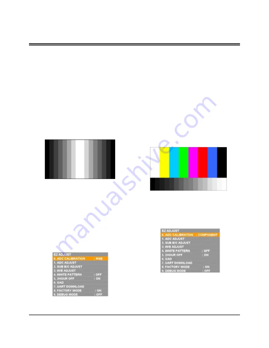
[gray pattern that left & right is black and center is white
signal (Refer below picture)].
3) Adjust by commanding AUTO_COLOR_ADJUST(0xF1)
0x00 0x02 instruction.
(2) Confirmation
1) We confirm whether “0xB6(RGB)” address of EEPROM
“0xA2” is “0xAA” or not.
2) If “0xB6(RGB)” address of EEPROM “0xB2” isn’t “0xAA”,
we adjust once more
3) We can confirm the ADC values from
“0xB0~0xB5(RGB)” addresses in a page “0xA2”
[
Manual ADC process using Service Remocon. After enter
Service Mode by pushing “ADJ” key, execute “ADC Adjust” by
pushing “
G
” key at “0. ADC CALIBRATION “.
4-2. COMPONENT Input ADC
(1) Component Gain/Offset Adjustment
1) Convert to Component in Input-source
I2C COMMAND : 0xF4 (SELECT_INPUT) 0x00 0x40
(COMPONENT)
cf. 0x10(TV), 0x20(AV), 0x40(COMPONENT),
0x60(RGB), 0x90(HDMI)
2) Signal equipment displays
Impress Resolution 480i
MODEL : 209 in Pattern Generator(480i Mode)
PATTERN : 8 in Pattern Generator(MSPG-925 SERISE)
3) Adjust by commanding AUTO_COLOR_ADJUST(0xF1)
0x00 0x02 instruction
4) Signal equipment displays
Impress Resolution 1080i
MODEL : 223 in Pattern Generator(1080i Mode)
PATTERN : 8 in Pattern Generator(MSPG-925 SERISE)
5) Adjust by commanding AUTO_COLOR_ADJUST(0xF1)
0x00 0x02 instruction
[
Manual ADC process using Service Remocon. After enter
Service Mode by pushing “ADJ” key, execute “ADC Adjust” by
pushing “
G
” key at “0. ADC CALIBRATION”.
Copyright©2008 LG Electronics. Inc. All right reserved.
Only for training and service purposes
LGE Internal Use Only
ADJUSTMENT INSTRUCTIONS


