11. EDID
(The Extended Display Identification Data )
/DDC
(Display Data Channel)
download
11-1. Profile
: To be possible for plug and play.
11-2. Required Test Equipment
(1) Adjusting PC with S/W for writing EDID Data.
(S/W : EDID TESTER Ver.2.5)
(2) A Jig for EDID Download.
(3) Cable : Serial(9Pin or USB) to D-sub 15Pin cable, D-sub
15Pin cable, DVI to HDMI cable.
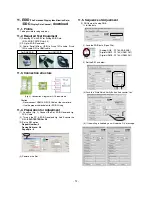
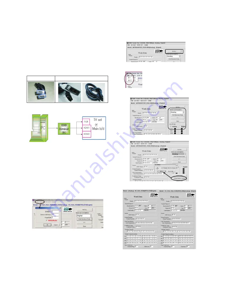
11-3. Connection structure
* Caution
- Never connect HDMI & D-SUB Cable at the same time.
- Use the proper cables below for EDID Writing.
11-4. Preparation for Adjustment
(1) As above (Fig. 2), Connect the Set, EDID Download Jig,
PC & Cable.
(2) Turn on the PC & EDID Download Jig. And Execute the
S/W :
EDID TESTER Ver 2.5
.
(3) Set up S/W option.
Repeat Number : 5
Device Address : A0
PageByte : 8
(4) Power on the Set.
11-5. Sequence of Adjustment
(1) DDC data of Analog-RGB
1) Init the data.
2) Load the EDID data.(Open File).
[ Analog-RGB : PP78A_RGB.ANA ]
[ Digital-HDMI1 : PP78A_HDMI1.DVI ]
[ Digital-HDMI2 : PP78A_HDMI2.DVI ]
3) Set the S/W as below.
(4) Push the “Write Data & Verify”button. And confirm “Yes”.
(5) If the writing is finished, you will see the “OK” message.
- 12 -
For RGB EDID
For HDMI EDID
(Fig. 2) Connection Diagram of DDC download
Open File
Open File
Содержание 42PC51
Страница 25: ...MEMO 25 ...
Страница 36: ......
Страница 37: ......
Страница 38: ......
Страница 39: ...MAIN TOP MAIN BOTTOM SIDE A V TOP SIDE A V BOTTOM IR LED CONTROL TOP CONTROL BOTTOM PRINTED CIRCUIT BOARD ...
Страница 40: ...Mar 2007 Printed in Korea P NO MFL38559902 ...


