20
206-4137
Installer Menu (Cont.)
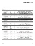
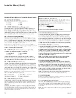
070 - FOR. CH-TIME (Channel-Time Display Foreground Color)
Set according to Color Chart:
0 = Black
3 = Cyan
6 = Yellow
1 = Blue
4 = Red
7 = White
2 = Green
5 = Violet
Note:
If foreground color and background color are the same,
the menu background will be transparent.
071 - BCK. CH-TIME (Channel-Time Display Background
Color)
Set according to Color Chart:
0 = Black
3 = Cyan
6 = Yellow
1 = Blue
4 = Red
7 = White
2 = Green
5 = Violet
Note:
If foreground color and background color are the same,
the menu background will be transparent.
073 - CH NOT AVBLE (Channel Not Available)
If set to 1 and item 028 CH. OVERIDE is set to 0, a “NOT AVAIL-
ABLE” message is displayed when directly accessing a channel
not in the channel scan list available in memory.
075 - REVERT CH (Revert to Start Channel)
If set to 1 and loss of MPI communication occurs, TV automati-
cally tunes to the specified Start Channel.
078 - UPN MSB (UPN Most Significant Byte)
User programmable number, most significant byte readable by
MPI command. Not linked to serial number.
079 - UPN MSB-1 (UPN Most Significant Byte-1)
User programmable number, most significant byte-1 readable by
MPI command. Not linked to serial number.
080 - UPN MSB-2 (UPN Most Significant Byte-2)
User programmable number, most significant byte-2 readable by
MPI command. Note: Not linked to serial number.
081 - UPN LSB (UPN Least Significant Byte)
User programmable number, least significant byte readable by
MPI command. Note: Not linked to serial number.
082 - CHKSM ERROR (Checksum Error)
Enforces rigid MPI checksum validation. Set to 1 for validation.
Set to 0 to disable (does not check checksum on MPI async port).
SPI is always checked.
083 - HANDSHK TIME (Handshake Time)
Adds an additional delay to the handshake time which is 64 msec,
thus relaxing MPI timing requirements to be compatible with PC-
based Windows controlled systems. Range is 0 - 5.
(Timeout = 25.5MS + [25.5 MS* Handshake time].)
084 - PERMANENT BLK (Permanent Block)
Allows Lock (Parental Control) blocking schemes to be permanent
by disabling the blocking hours function. Set to 1 to install Paren-
tal Control restrictions permanently. Set to 0 for user-specified
hours control of blocking schemes.
087 - REAR RGB EN. (Rear RGB Enable)
Controls access to rear RGB input on TV. Set to 0 to disable RGB
input. Set to 1 (LD65xH) / 2 (LG710H) to enable for PC RGB
input. Set to 17 (LD65xH) / 18 (LG710H) to initiate a one-time
automatic configuration after an AC power cycle; otherwise,
automatic adjustment will be performed each time the RGB input
is accessed.
088 - EN NOISE MUTE (Enable Noise Mute)
If set to 1, audio mutes if no signal is present.
090 - KEY LOCK
If set to 1, front keyboard buttons Channel, Volume, and Cap-
tions are disabled, Power button remains enabled. If set to 0, front
keyboard Channel, Volume, Captions and Power buttons are all
enabled.
091 - YPrPb2 EN. (HDMI2 Enable)
Set to 0 to disable display panel HDMI2 input. Set to 1 to enable
DTV mode. Set to 2 to enable PC mode.
093 - RJP AVAILABLE (Remote Jack Pack Available)
•
0 = Remote jack pack is not available or disabled.
•
1 = Legacy Model RJPs: HDMI Mode
Enables RJP feature for use with full cable bundle models. In
this mode, when an HDMI source is connected to the RJP, both
digital video and audio are expected via the HDMI cable. If no
digital audio is present, no audio will be heard.
•
2 = Legacy Model RJPs: DVI Mode
Enables RJP feature for use with full cable bundle models. In
this mode, when an HDMI/DVI source is connected to the RJP,
only digital video is expected via the HDMI cable. Analog audio
is provided via a separate cable, from the source, connected to
an RJP AUDIO IN. If no analog audio cable is connected, tuner
audio will be heard.
•
5 = Scaler Model RJPs: HDMI Mode
Enables RJP feature for use with reduced cable bundle models.
In this mode, when an HDMI source is connected to the RJP,
both digital video and audio are expected via the HDMI cable. If
no digital audio is present, no audio will be heard.


