22
EXTERNAL EQUIPMENT SETUP
EXTERNAL EQ
UIPMENT SETUP
G
G
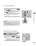
If both S-VIDEO and VIDEO sockets have been connected to
the S-VHS VCR simultaneously, only the S-VIDEO can be
received.
NOTE
!
VIDEO
L
R
S-VIDEO
VIDEO
OUTPUT
SWITCH
ANT IN
ANT OUT
EJECT
PCMCIA
CARD SLOT
RS-232C IN
AUDIO
AV 1
AV 2
EJECT
PCMCIA
CARD SLOT
RS-232C IN
ANTENNA
IN
AUDIO
VIDEO
AV IN 3
V IN 3
L/L/
MONOMONO
R
AUDIOAUDIO
VIDEOVIDEO
S-VIDEO
S-VIDEO
AV IN 3
L/
MONO
R
AUDIO
VIDEO
S-VIDEO
ANTENNA
IN
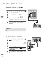
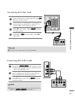
Connecting with a S-Video cable
Connect the S-VIDEO output of the VCR to the S
S --
V
V II D
D E
E O
O input on the TV. The picture quality is
improved; compared to normal composite (RCA cable)
input.
Connect the audio outputs of the VCR to the A
AU
UD
DIIO
O
input jacks on the TV.
Insert a video tape into the VCR and press PLAY on the
VCR. (Refer to the VCR owner’s manual.)
Select
AV3
input source using the IIN
NP
PU
UT
T button on the
remote control.
2
3
4
1
1
2
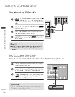
DIGITAL AUDIO OUT SETUP
Sending the TV’s audio signal to external audio equipment via the Digital Audio Output (Optical) port.
G
Do not look into the optical output port. Looking at the
laser beam may damage your vision.
CAUTION
RGB(PC)
AUDIO
(RGB/DVI)
RGB IN
AV 1
AV 2
EJECT
PCMCIA
CARD SLOT
RS-232C IN
RVICE)
2
HDMI IN
(OPTICAL)
DIGITAL AUDIO OUT
ANTENNA
IN
COMPONENT IN
AUDIO
VIDEO
Connect one end of an optical cable to the TV Digital
Audio (Optical) Output port.
Connect the other end of the optical cable to the digi-
tal audio (optical) input on the audio equipment.
Set the “TV Speaker option - Off ” in the AUDIO menu.
(
G
p
p..8
88
8
). Refer to the external audio equipment
instruction manual for operation.
2
3
1
1
2

