background image

- 3 -

SAFETY PRECAUTIONS

Many electrical and mechanical parts in this chassis have special safety-related characteristics. These parts are identified by      in
the Schematic Diagram and Replacement Parts List. 
It is essential that these special safety parts should be replaced with the same components as recommended in this manual to
prevent X-RADIATION, Shock, Fire, or other Hazards. 
Do not modify the original design without permission of manufacturer.

General Guidance

An 

isolation Transformer should always be used

during

the servicing of a receiver whose chassis is not isolated from
the AC power line. Use a transformer of adequate power rating
as this protects the technician from accidents resulting in
personal injury from electrical shocks.

It will also protect the receiver and it's components from being
damaged by accidental shorts of the circuitry that may be
inadvertently introduced during the service operation.

If any fuse (or Fusible Resistor) in this TV receiver is blown,
replace it with the specified.

When replacing a high wattage resistor (Oxide Metal Film
Resistor, over 1W), keep the resistor 10mm away from PCB.

Keep wires away from high voltage or high temperature parts.

Due to high vacuum and large surface area of picture tube,
extreme care should be used in 

handling the Picture Tube

.

Do not lift the Picture tube by it's Neck.

X-RAY Radiation

Warning: 

To determine the presence of high voltage, use an accurate
high impedance HV meter.

Adjust brightness, color, contrast controls to minimum. 
Measure the high voltage. 
The meter reading should indicate 
23.5 

±

1.5KV: 14-19 inch, 26

±

1.5KV: 19-21 inch,

29.0

±

1.5KV: 25-29 inch, 30.0

±

1.5KV: 32 inch

If the meter indication is out of tolerance, immediate service
and correction is required to prevent the possibility of
premature component failure.

Before returning the receiver to the customer, 

always perform an 

AC leakage current check

on the exposed

metallic parts of the cabinet, such as antennas, terminals, etc.,
to be sure the set is safe to operate without damage of
electrical shock. 

Leakage Current Cold Check(Antenna Cold Check)

With the instrument AC plug removed from AC source,
connect an electrical jumper across the two AC plug prongs.
Place the AC switch in the on position, connect one lead of
ohm-meter to the AC plug prongs tied together and touch other
ohm-meter lead in turn to each exposed metallic parts such as
antenna terminals, phone jacks, etc. 
If the exposed metallic part has a return path to the chassis, the
measured resistance should be between 1MΩ and 5.2MΩ. 
When the exposed metal has no return path to the chassis the
reading must be infinite.
An other abnormality exists that must be corrected before the
receiver is returned to the customer.

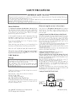
Leakage Current Hot Check 

(See below Figure) 

Plug the AC cord directly into the AC outlet.

Do not use a line Isolation Transformer during this check. 

Connect 1.5K/10watt resistor in parallel with a 0.15uF capacitor
between a known good earth ground (Water Pipe, Conduit, etc.)
and the exposed metallic parts.
Measure the AC voltage across the resistor using AC
voltmeter with 1000 ohms/volt or more sensitivity.
Reverse plug the AC cord into the AC outlet and repeat AC
voltage measurements for each exposed metallic part. Any
voltage measured must not exceed 0.75 volt RMS which is
corresponds to 0.5mA.
In case any measurement is out of the limits specified, there is
possibility of shock hazard and the set must be checked and
repaired before it is returned to the customer.

Leakage Current Hot Check circuit

The source of X-RAY RADIATION in this TV receiver is the
High Voltage Section and the Picture Tube.
For continued X-RAY RADIATION protection, the
replacement tube must be the same type tube as specified in
the Replacement Parts List.

1.5 Kohm/10W

To Instrument’s
exposed 
METALLIC PARTS

Good Earth Ground
such as WATER PIPE,
CONDUIT etc.

AC Volt-meter

IMPORTANT SAFETY NOTICE

0.15uF

Copyright©2007 LG Electronics.Inc. All right reserved.
Only for training and service purposes.

LGE Internal Use Only

Содержание 21FX4 AG

Страница 1: ...CHASSIS READ THE SAFETY PRECAUTIONS IN THIS MANUAL CHASSIS MC 059B MODEL 21FX4AG AGE AGS AL MODEL 21FX4AG AGE AGS AL TH website http biz LGservice com e mail http www LGEservice com techsup html Oct 2007 Printed in China P NO 3828VD0235Q Internal Use Only ...

Страница 2: ...ECIFICATIONS 7 ADJUSTMENT 9 PRINTED CIRCUIT BOARD 14 TROUBLE SHOOTING 16 BLOCK DIAGRAM 20 EXPLODED VIEW 22 EXPLODED VIEW PARTS LIST 23 REPLACEMENT PARTS LIST 24 Copyright 2007 LG Electronics Inc All right reserved Only for training and service purposes LGE Internal Use Only ...

Страница 3: ...ic parts of the cabinet such as antennas terminals etc to be sure the set is safe to operate without damage of electrical shock Leakage Current Cold Check Antenna Cold Check With the instrument AC plug removed from AC source connect an electrical jumper across the two AC plug prongs Place the AC switch in the on position connect one lead of ohm meter to the AC plug prongs tied together and touch o...

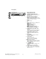
Страница 4: ... D E Programme Up Down selects a programme or a menu item switches the set on from standby scans programmes automatically F G Volume Up Down adjusts the volume adjusts menu settings OK accepts your selection or displays the current mode 6 Q VIEW returns to the previously viewed programme 7 PSM Picture Status Memory recalls your preferred picture setting 8 FAVOURITE selects a favorite programme 9 T...

Страница 5: ...ound Status Memory option recalls your preferred sound setting 16 SURROUND º º option selects surround sound No function COLOURED BUTTONS These buttons are used for teletext only TELETEXT models or programme edit POWER MUTE 1 2 3 4 5 6 7 8 9 MENU INDEX TV AV 0 EYE Q VIEW LIST I II PR PR OK VOL VOL PSM SSM SLEEP PICTURE SOUND TURBO FAVOURITE TV 10 11 12 13 14 16 15 Copyright 2007 LG Electronics Inc...

Страница 6: ...ut sockets of external equipment to these sockets 7 HEADPHONE SOCKET option Connect the headphone plug to this socket 8 EYE option adjusts picture according to the sur rounding conditions 9 TV AV option selects TV or AV mode clears the menu from the screen switches the set on from standby 10 Function option selects volume EYE option picture items or brief auto programme while the menus not display...

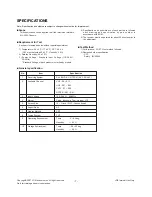
Страница 7: ...e adjustment V Test Method 1 Performance LGE TV test method followed 2 Demanded other specification CCC Safety IEC60065 7 A General specification SPECIFICATIONS Note Specification and others are subject to change without notice for improvement Item Receiving System Available Channel Input Voltage Market Screen Size Aspect Ratio Display Method Tuning System Operating Environment Storage Environment...

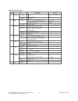
Страница 8: ...cture Sound LG Code NEC System Storage Normal Turbo Storage System Channel Fine Search Name Copy Move Delete Skip 8 Channel Dynamic Standard Mild Game User Contrast Brightness Color Sharpness Tint NTSC M Only Flat Music Movie Speech User 0 100 100 400 1K 4K 10K Off On Pr 1 VOL 30 Off On On Off English Russia English Indonesia Thai Vietnam TV AV1 AV2 On Off Remark Rear1 Front1 CVBS L R Rear 7EA Fro...

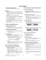
Страница 9: ...n adjustment mode 3 Adjust the Screen Vol of FBT to appear Horizontal Line and adjust the Screen Vol of FBT at disappear point Horizontal Line Press the Enter A key to exit SVC mode 5 Purity and Convergence Adjustment 5 1 Purity Adjustment 1 Adjustment Preparation 1 Receive Red Raster Pattern for purity adjustment 2 Demagnetize the CPT and Cabinet with a degaussing coil 2 Horizontal Line Adjustmen...

Страница 10: ... VP7 and Y data with B DRIVE VP9 to have the color temperature as shown below c Make the picture luminance 4 5Ft L by changing the CONTRAST and BRIGHTNESS d Adjust X data of low light with R BIAS VP4 and Y data with B BIAS VP6 to have the color temperature as shown below e Repeat steps a d until both low and high light have same readings as shown below f Check the adjusted color coordinates with w...

Страница 11: ...D MUTE GAME OPTION2 TURBO ARC 200PR BLUEBACK TURBO AT HOTEL SHARP DVDN OPTION3 FM TRANS FM HIGH NTSC AV PSEU SYNC KI A2 SW LNA SWOOFER OPTION 4 SYSTEM SND MODE AV LOC KEY COLOR T PLL DIV MTS LEV OPTION 5 FM PRE NICAM PRE SCART PRE A2 FM TH FIRST TH ZWT TH INITIAL 0 0 0 0 0 1 1 0 0 0 0 1 1 0 0 1 0 0 1 1 1 0 0 0 4 1 2 1 1 31 22 6 13 0 5 15 2 REMARK DVD function 1 Yes 0 No T P T S function in MENU Di...

Страница 12: ...e shoot Adjustment Over shoot Adjustment Y Gamma start point Select DC Restoration Select Black Stretch Start Point Select Black Stretch Gain Select C Bypass C Kill On C Kill Off Color Killer Operational Point R B Gain Balance R B Angle B Y DC Level R Y DC Level Video Level OVER MOD SW OVER MOD LEVEL Tint Through Range 0 63 0 31 0 15 0 127 0 255 0 255 0 255 0 127 0 15 0 127 0 31 0 31 0 7 0 7 0 7 0...

Страница 13: ...f sync sepalation G Y Amplitude Color on off on Half tone Mode Overmodulation circit Type APC Offset current IF video level offset 5 74MHz FM Det IF VCO freerun frequency Equalizer Bell filter Equalizer circuit Bell filter adjust SECAM Killer circuit disable SECAM Killer circuit enable OSD Contrast OSD Position Range 0 3 0 3 0 3 0 3 0 3 0 3 0 1 0 1 0 1 0 1 0 1 0 1 0 1 0 1 0 3 0 3 0 1 0 1 0 1 0 1 0...

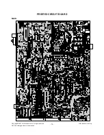
Страница 14: ... 14 PRINTED CIRCUIT BOARD MAIN Copyright 2007 LG Electronics Inc All right reserved Only for training and service purposes LGE Internal Use Only ...

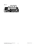
Страница 15: ... 15 SIDE A V Copyright 2007 LG Electronics Inc All right reserved Only for training and service purposes LGE Internal Use Only ...

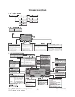
Страница 16: ...s In case of influx NOISE R C is not operate Maneuver defectiveness 1 TV FUNCTIONAL 2 TU IF SECTION 3 VIDEO PROCESSING TROUBLE SHOOTING Copyright 2007 LG Electronics Inc All right reserved Only for training and service purposes LGE Internal Use Only ...

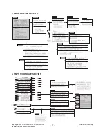
Страница 17: ... 17 4 SMPS PRIMARY SECTION 5 SMPS SECONDARY SECTION Copyright 2007 LG Electronics Inc All right reserved Only for training and service purposes LGE Internal Use Only ...

Страница 18: ... 18 6 VERTICAL SECTION 7 HORIZONTAL SECTION Copyright 2007 LG Electronics Inc All right reserved Only for training and service purposes LGE Internal Use Only ...

Страница 19: ...8 SOUND PROCESSING SECTION 19 9 CPT DRIVE SECTION Copyright 2007 LG Electronics Inc All right reserved Only for training and service purposes LGE Internal Use Only ...

Страница 20: ... 20 BLOCK DIAGRAM HIC291 Copyright 2007 LG Electronics Inc All right reserved Only for training and service purposes LGE Internal Use Only ...

Страница 21: ... 21 MEMO Copyright 2007 LG Electronics Inc All right reserved Only for training and service purposes LGE Internal Use Only ...

Страница 22: ... EXPLODED VIEW 112 913 170 150 153 943 400 P801 520 300 600 120 310 320 330 510 700 option Copyright 2007 LG Electronics Inc All right reserved Only for training and service purposes LGE Internal Use Only ...

Страница 23: ...TTON POWER RN 21FX40 ABS HF 380 1KEY 5020V01121A Button MOLD ABS POWER 21FX4 ABS NON LGESY LOCAL 400 3809900123B BACK COVER ASSEMBLY 21FX4RG TB DVD 1PHONE IN LOCAL 3809V00539F BACK COVER ASSEMBLY DVD 1PHONE HIPS 51SF BK SY N ALLIED 3809V00615A D F Cover Assembly 21FX5 DVD 1PHONE SY LOCAL 510 6871VSN901D PWB PCB ASSEMBLY SUB M I MC059A LGEIN SVC CPT BOARD 15 17 20 21 520 68719MM156D PWB PCB ASSEMBL...

Страница 24: ...ION IC02 IC301 IC501 IC601 IC661 IC751 IC801 IC802 IC803 IC804 IC805 Q10 Q101 Q102 Q111 Q16 Q241 Q301 Q401 Q402 Q403 Q502 Q601 Q671 Q672 Q801 Q813 Q901 Q902 Q903 D111 D301 D302 D303 D403 D405 D501 D502 D505 D601 D602 D603 D604 0IMMR00010A 0IPRPSA006B 692792013AA 0IPMGSA024C 0IPRP00581A 0IPRPSA018A 0IPMGSK016B 0IPRPKD003A 0IKE780500Q 0IMCRKE002B 0ISK110000A 0TR319809AA 0TR319709AB 0TR319809AA 0TR10...

Страница 25: ...C545 C550 C56 C602 C603 C604 C605 C606 C607 C608 C609 C610 C611 C612 C613 C614 C653 C654 C655 C656 C657 C658 C659 C660 C662 C663 C664 C665 C667 C668 C670 C671 C673 C675 C676 C678 C680 C681 C682 C685 C687 0CE225DK618 0CE474DK618 0CN1040K949 0CQ4731N509 0CN1030F679 0CN1030F679 0CE105DK618 0CN1010K519 0CN1010K519 0CE475DR618 0CQ1831N509 0CK2230K945 0CX4700K409 0CN4710K519 0CE337DH618 0CE475DK618 0CQ2...

Страница 26: ...RIPTION L401 L402 L501 L663 L664 L665 L802 T403 T803 C1 C2 C3 C4 C5 P101 P1203A P1206A P601 P602 C221 C222 C233 C234 C286 C287 FR301 FR401 FR403 FR501 FR825 J511 L212 L280 L281 R1 R101 R102 R103 R104 R105 R108 R109 R110 R111 R112 R113 R1221 R1222 150 L01R 6140VB0001F 0LA0122K119 0LA0102K119 0LA0102K119 0LA0102K119 150 C02F 151 C02B 6170VMCA13X 366 036B 387 603E 387 917J 6631V25014H 6631V25034H 366...

Страница 27: ... R510 R512 R513 R514 R515 R516 R519 R521 R522 R523 R524 R525 R526 R527 R529 R530 R530 R531 R531 R532 R534 R536 R537 R547 R550 R552 R553 R554 R555 R556 R561 R562 R563 R564 R565 R566 R58 R601 R602 R603 R604 R605 R607 R609 R610 R611 R612 R613 0RD1000F609 0RD1000F609 0RD3901F609 0RD3901F609 0RD3901F609 0RN4701F409 0RD1200F609 0RD1000F609 0RD0102F609 0RD1000F609 0RD1202F609 0RD7501F609 0RD2402F609 0RD2...

Страница 28: ...1 2 W 7 0 5 00 TA52 1 5K OHM 1 2 W 7 0 5 00 TA52 1 5K OHM 1 2 W 7 0 5 00 TA52 LOCA NO PART NO DESCRIPTION R921 R922 R922 R923 ZD505 SW11 SW12 SW13 SW14 SW15 SW16 SW801 FB801 L804 T802 X1 X501 X661 Z111 Z601 JA01 JA1201 JA1202 P201 P401 P610 P801 P802 P901 A1 A2 A3 B1 0RD1000F609 0RD4300F609 0RD4300F609 0RS1802K607 0RD1004F609 140 315A 140 315A 140 315A 140 315A 140 315A 140 315A 6600VM1001A 125 02...

Страница 29: ... FUSE 4000MA 250 V 5 2X20 LED LITEON LTL 4223 BK RED 19MCD SOCKET CIRC CPT PCS030A 8PIN 14 360 FBT BSC25 N0352 21 THERMISTOR PTC J502P84D140M290Q THERMISTOR NTC KL15L040 40OHM 15 2900K TUNER TAEW G013D LGIT MULTI FS VARISTOR SVC621D 14A ILJIN 620V 0 BOX DWR2 676 524 503 2 COLOR 21FX4 LOCA NO PART NO DESCRIPTION Copyright 2007 LG Electronics Inc All right reserved Only for training and service purp...

Страница 30: ...P NO 3854VA0196B S1 LGE Internal Use Only Copyright 2007 LG Electronics Inc All right reserved Only for training and service purposes ...

Страница 31: ...SVC SHEET 3854V A0196B S ...

Отзывы: