Physik
Chemie
⋅
Biologie
Technik
LEYBOLD DIDACTIC GMBH
6/95-Pr/Sf-
Gebrauchsanweisung
332 101
Instruction Sheet
The device can be used to demonstrate the gravitational
a ttractive force between masses and to determine the gra-
vitational constant
f.
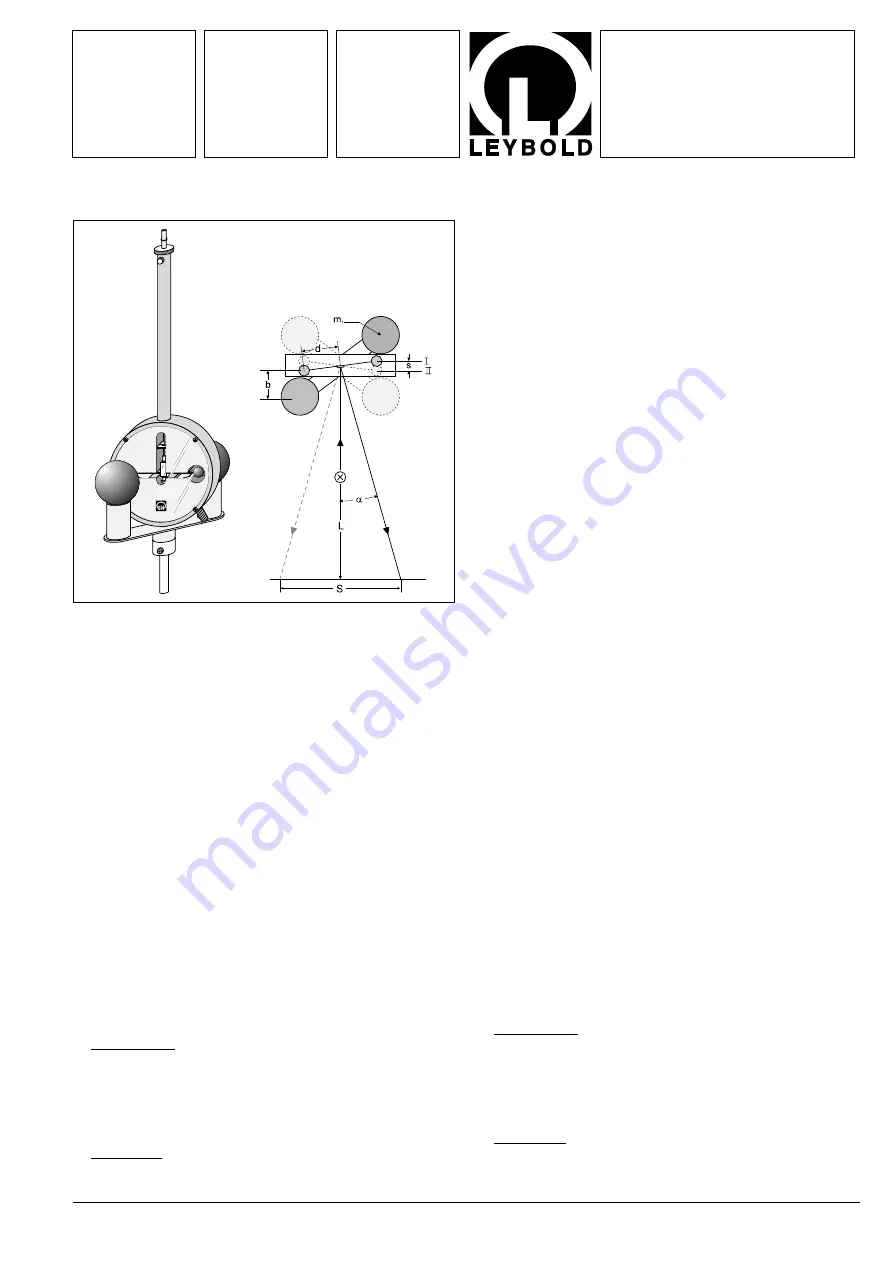
Measurement principle (Fig.1)
The static equilibrium (position I) of a torsion pendulum with a
period of approx. 10 min. is disturbed by a change in position
of the outer masses
m
1
, which affect the dumbbell-shaped
pendulum body. The oscillations become damped and the
pendulum takes up a new equilibrium position (position 2). The
angle between the two positions is a measure of the active
gravitational force.
The oscillation of the pendulum, which is equipped with a con-
cave mirror, is indicated by a light pointer. This is possible using
- visible light directly on a mm-scale or
- infrared light along with the IR position detector (332 11). The
latter enables the measurement values to be plotted or
evaluated by computer.
The gravitational constant
f can be obtained from the oscillation
curve with respect to time, the mass
m
1
and the geometry of the
arrangement using either the end deflection method or (in a
quicker process) the acceleration method.
In the
end deflection method the torsion pendulum period T and
the distance
S separating the light pointer positions are evaluated
for the two equilibrium positions:
f
=
π
2
⋅
b
2
⋅
d
⋅
S
m
1
⋅
T
2
⋅
L
(I)
In the
acceleration method, the acceleration of the torsion
pendulum
a = 2s/t
2
is evaluated using the masses
m
1
after the
equilibrium position has been disturbed:
f
=
S
⋅
d
⋅
b
2
2
m
1
⋅
t
2
⋅
L
(II)
Das Gerät dient zur Demonstration der durch Gravitationskräfte
verursachten Massenanziehung und zur Bestimmung der Gra-
vitationskonstanten
f.
Meßprinzip (Fig.1)
Ein Torsionspendel mit einer Schwingungsdauer von etwa
10 min wird durch eine Positionsänderung der äußeren Massen
m
1
, die auf den hantelförmigen Pendelkörper wirken, in seinem
statischen Gleichgewicht (Stellung I) gestört; es führt gedämpfte
Schwingungen aus und schwingt in eine neue Gleichgewichtsla-
ge (Stellung II) ein. Der Winkel zwischen beiden Gleichgewichtsla-
gen ist ein Maß für die wirksame Gravitationskraft.
Die Schwingung des Pendels, an dem ein Hohlspiegel ange-
bracht ist, wird durch eine Lichtmarke angezeigt, wahlweise
- mit sichtbarem Licht direkt auf einer mm-Skala oder
- mit Infrarot-Licht unter Verwendung des IR-Position-De-
tectors (332 11), der eine Schreiberaufzeichnung oder eine
computerunterstützte Meßwerterfassung ermöglicht.
Aus dem zeitlichen Verlauf der Schwingung, der Masse
m
1
und
der Geometrie der Anordnung ermittelt man die Gravitationskon-
stante
f entweder nach der Endausschlagmethode oder (bei ver-
kürztem Meßverfahren) nach der Beschleunigungsmethode.
Bei der
Endausschlagmethode werden die Schwingungsdau-
er
T des Torsionspendels und der Abstand S zwischen den
Lichtzeigerpositionen für die beiden Gleichgewichtslagen aus-
gewertet:
f
=
π
2
⋅
b
2
⋅
d
⋅
S
m
1
⋅
T
2
⋅
L
(I)
Bei der
Beschleunigungsmethode wird die Beschleunigung
a = 2s/t
2
des Torsionspendels nach der Störung seiner Gleich-
gewichtslage durch die Massen
m
1
ausgewertet:
f
=
S
⋅
d
⋅
b
2
2
m
1
⋅
t
2
⋅
L
(II)
Gravitations-Drehwaage
Gravitation Torsion balance
Fig. 1
Gravitations-Drehwaage (332 101) sowie schematische Dar-
stellung zum Meßprinzip
Gravitation torsion balance (332 101) and schematic diagram
of measuring principle


