Diagnostic aids
3-39
7014-xxx
7.
Print the Quick Test page again and check that the darkest line in the center graph is equal to zero. If it is,
then check to see if the left, top, and bottom margins are detected. If it is not, then repeat step 5.
Note:
The alignment of the left margin positions the black plane to the right or left. The alignment of the right
margin does not alter the margins and should only be used to adjust the printhead.
Printhead assembly mechanical adjustment
A printhead needs to be correctly positioned after it has been removed. Use a pencil to mark the screw locations
of the old printhead on the metal frame. Align the new printhead relative to the location of the old printhead.
Note:
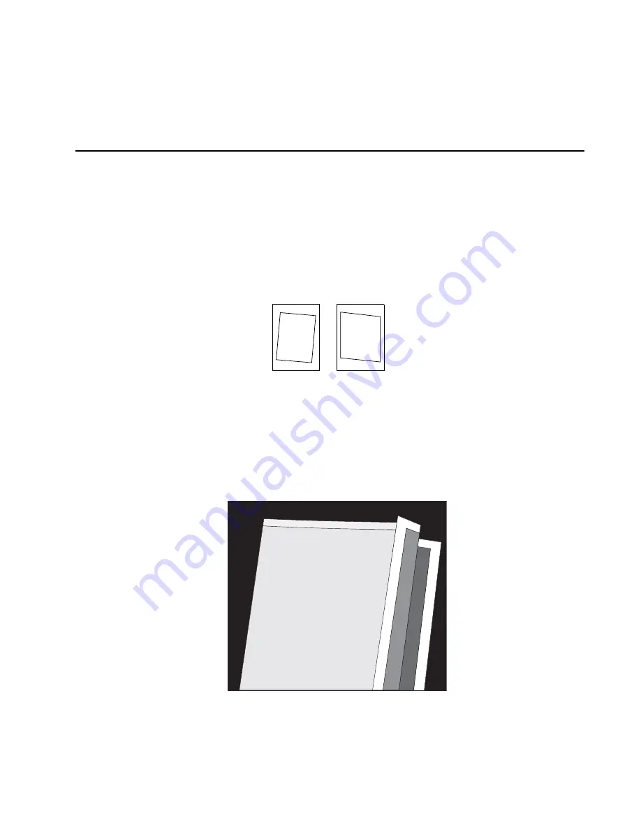
Skew is caused by a sheet being fed through the printer while misaligned. The entire image is rotated
relative to the sheet edges. However, a mechanically misaligned printhead causes the horizontal lines to appear
skewed, while the vertical lines remain parallel to the vertical edges. There are no adjustments for skew. Check
the pick roll (paper pick assembly) for wear, the paper path for obstructions, the fuser for proper setting, and the
tray paper guides for fit to the media.
To adjust the printhead:
1.
Enter the Diagnostics Menu. See
“Entering Diagnostics menu” on page 3-17
.
2.
Select
PRINT TESTS
.
3.
Select
Tray 1
.
4.
Select
Single
.
5.
Fold the printed test page on the left side so that a few millimeters of grid lines wrap around the outside of
the fold. See photo below.
6.
Fold a second vertical fold near the center so that the left side top edge aligns with the right side top edge.
Printhead
misalignment
Paper feed
skew
Содержание X46 Series
Страница 10: ...x Service Manual 7014 xxx...
Страница 15: ...Notices and safety information xv 7014 xxx...
Страница 16: ...xvi Service Manual 7014 xxx...
Страница 22: ...xxii Service Manual 7014 xxx...
Страница 153: ...Diagnostic aids 3 47 7014 xxx 3 Remove the jam 4 Close the rear door 5 Close the front door 6 Touch Continue...
Страница 162: ...3 56 Service Manual 7014 xxx...
Страница 174: ...4 12 7014 xxx 2 Remove the three screws B securing the top of the controller shield B...
Страница 184: ...4 22 7014 xxx 6 Remove the screw D from the gear E 7 Remove the plastic bushing F...
Страница 185: ...Repair information 4 23 7014 xxx 8 Use a screwdriver to pop the retainer clip G loose from the gear 9 Remove the gear H...
Страница 188: ...4 26 7014 xxx 6 Disconnect the MPF from the lower front cover 7 Disconnect the fuser link A from the front access door A...
Страница 191: ...Repair information 4 29 7014 xxx 5 Disconnect the AC cable C 6 Disconnect the thermistor cable D C B D...
Страница 194: ...4 32 7014 xxx 2 Carefully pull the scanner front cover away from the tub assembly...
Страница 207: ...Repair information 4 45 7014 xxx 5 Remove the three screws B from the left door mount B...
Страница 210: ...4 48 7014 xxx 8 Use a screwdriver to pop the inner shaft lock B loose 9 Remove the inner shaft lock C...
Страница 221: ...Repair information 4 59 7014 xxx 7 Open the front access door and remove the lower paper guide...
Страница 223: ...Repair information 4 61 7014 xxx 5 Remove the three screws B from the left side of the printer B...
Страница 255: ...Repair information 4 93 7014 xxx 13 Disconnect LSU HSYNC extension cable at the connector in the middle of the cable...
Страница 256: ...4 94 7014 xxx 14 Remove the three screws A from the left rear frame assembly A A A...
Страница 257: ...Repair information 4 95 7014 xxx 15 Remove the three screws B from the right rear frame assembly B B B...
Страница 278: ...4 116 7014 xxx...
Страница 290: ...7 2 Service Manual 7014 xxx Assembly 1 Covers 3 11 7 13 5 16 9 15 2 10 6 17 4 12 8 14 1 17 18...
Страница 292: ...7 4 Service Manual 7014 xxx Assembly 2 Imaging 3 11 7 13 5 16 9 15 2 10 6 4 12 8 14 1...
Страница 294: ...7 6 Service Manual 7014 xxx Assembly 3 Tray assemblies 3 2 1 5 4...
Страница 296: ...7 8 Service Manual 7014 xxx Assembly 4 Electronics 2 1 10 11 12 7 13 9 6 14 2 5 8 3 4 16 15 17...
Страница 298: ...7 10 Service Manual 7014 xxx Assembly 5 Frame 7 1 2 5 6 7 12 8 See instruction sheet in the FRU 9 10 11 3 4 3...
Страница 302: ...7 14 Service Manual 7014 xxx...
Страница 306: ...I 4 Service Manual 7014 xxx...
Страница 309: ...Part number index I 7 7014 xxx 56P0558 RJ11 Cable w Toroids 7 12 7377732 Relocation Kit 7 12...
Страница 310: ...I 8 Service Manual 7014 xxx...


