background image

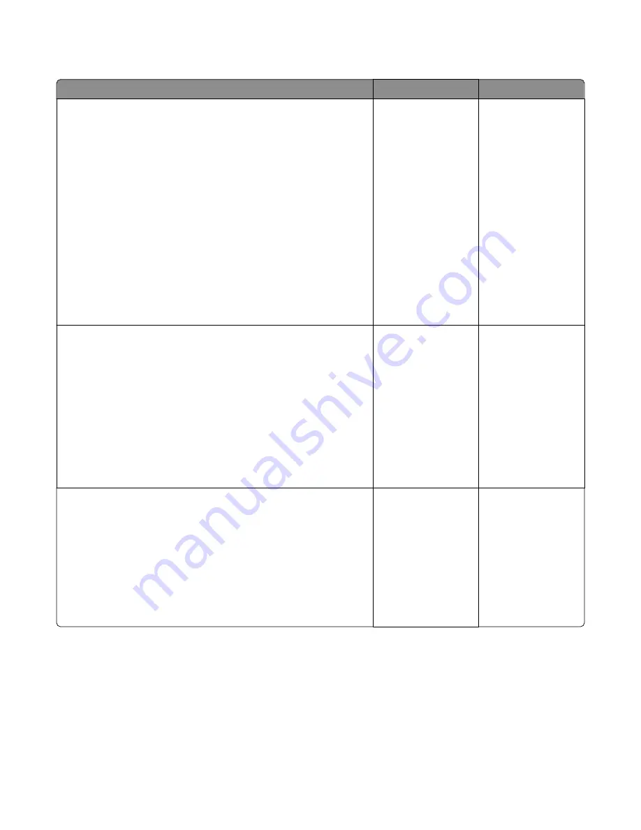
HCIT lift plate failure service check

Action

Yes

No

Step 1
Remove the media tray from the HCIT option and do the following:

Remove all media and check the paper guides for damage. Move the 

paper guide and verify if it can move freely from one position to 

another.

Check the media size finger flag for damage.

Check the elevator plate. Manually lower down the elevator plate and 

check if it springs back to its original position.

Check the elevator tension cables if there are problems.

Check the elevator gears for damage.

Manually turn the drive gear and check if the other gears engaged to 

it will also turn. *Check if the tray can be inserted properly into the 

HCIT option.

Are the above components ok?

Go to step 2.

Replace the media tray. 

Go to 

“HCIT removal” 

on page 414

.

Step 2
Remove the media tray and do the following:

Check the lift drive gears for damage. Manually turn the gears, and 

check if it causes the lift drive motor encoder to turn.

Open the right cover and check the motor connections. Check the 

motor cables for damage. If there is a problem with the lift drive motor, 

then replace it. See 

“HCIT lift drive motor removal” on page 427

.

Remove the left cover, and reseat the connector (J1) on the controller 

board. POR the machine.

Does the error remain?

Go to step 3.

The problem is solved.

Step 3
Remove the media tray from the HCIT option and do the following:

Check if there is no problem moving the tray input guides.

Manually push the media size sensor flags and check if it would spring 

back to its original position.

Check the sensor (HCIT media guide) for damage. Make sure all 

obstructions are removed.

Are the above components ok?

Go to step 4.

Replace the HCIT 

drawer assembly. Go to 

“HCIT drawer 

assembly removal” on 

page 414

.

4063

Diagnostic information

133

Содержание MS71 Series

Страница 1: ...Lexmark MS81x MS71x Printer Machine Type 4063 2xx 4x0 63x 83x Service Manual Start diagnostics Maintenance Safety and notices Trademarks Index October 18 2012 www lexmark com ...

Страница 2: ...o a product program or service is not intended to state or imply that only that product program or service may be used Any functionally equivalent product program or service that does not infringe any existing intellectual property right may be used instead Evaluation and verification of operation in conjunction with other products programs or services except those expressly designated by the manu...

Страница 3: ...Data security notice 33 Tools required for service 33 Diagnostic information 35 Troubleshooting overview 35 Performing the initial troubleshooting check 35 Error code number key 36 Power on Reset POR sequence 36 Using Safe Mode 37 Fixing print quality issues 37 Initial print quality check 38 Gray background on prints 38 Printer is printing blank pages 39 Printer is printing solid black pages 40 Re...

Страница 4: ...ensor narrow media static jam service check 65 Sensor fuser exit miscellaneous jam service check 66 Fuser ID chip control jam service check 66 203 paper jams 67 Upper redrive motor control jam service check 68 230 paper jams 68 Sensor duplex path static jam service check 71 Sensor duplex path early arriving jam service check 72 Sensor duplex path never or late arriving jam service check 73 Sensor ...

Страница 5: ...ce check 110 HVPS cooling fan service check 111 Miscellaneous cooling fan service check 111 Firmware and or system electronics errors 900 999 99 111 9xx error messages 112 System software error service check 115 NVRAM mismatch failure service check 120 Input output option hardware errors 121 3xx error messages 300 399 99 121 250 550 sheet transport motor failure service check 126 250 550 sheet med...

Страница 6: ...e service check 194 Option tray symptoms 195 250 550 sheet media type error service check 196 250 550 sheet tray undetected service check 198 HCIT incorrect media error service check 199 HCIT media type error service check 201 HCIT undetected service check 203 HCIT media low undetected service check 204 Finisher side door error service check 206 Mailbox incorrect bin exit service check 208 Finishe...

Страница 7: ...iverter Test 229 FINISHER TESTS 229 Staple Test 229 Hole Punch Test 230 Feed Test finisher 230 Finisher Sensor Test 230 BASE SENSOR TEST 231 DEVICE TESTS 231 Quick Disk Test 231 Disk Test Clean 232 Flash Test 232 PRINTER SETUP 232 Defaults 232 Printed Page Count 233 Permanent Page Count Perm page count 233 Processor ID 233 Engine Setting x 234 Edge to Edge 234 Parallel Strobe Adjustment Par 1 Stro...

Страница 8: ...0 Menu Settings Page 240 Event Log 240 Size sensing 240 Panel Menus 241 PPDS Emulation 241 Download Emuls 241 Safe Mode 241 Factory Defaults 242 Energy Conserve 242 Paper Prompts 242 Envelope Prompts 243 Action for Prompts 243 Jobs on Disk 244 Disk Encryption 244 Erase All Information on Disk 244 Wipe All Settings 245 Font Sharpening 245 Require Standby 245 A5 Loading 245 UI Automation 246 LES App...

Страница 9: ...act connector 260 Horizontal sliding contact connector 263 Low Insertion Force LIF connector 266 Adjustments 267 Media aligner roller adjustment 269 Polygon printhead mechanical registration adjustment 270 Removal procedures 272 Base printer cover removals 273 Left cover removal 273 Rear lower cover removal 276 Top cover removal 278 Right cover removal 278 Rear door removal 280 Base printer front ...

Страница 10: ...front flap removal 328 Duplex rear flap removal 329 Left frame extension removal 330 Media tray removal 332 Pick roller assembly removal 333 Right frame extension 334 Sensor duplex path removal 335 Sensor tray 1 media out removal 336 Separator roller assembly removal 338 Base printer left removals 339 Controller board removal 340 Controller board access cover removal 341 Controller board access sh...

Страница 11: ...ia tray front cover removal 398 Drawer pick roller removal 399 Sensor pick roll position removal 399 Drawer assembly rear cover removal 400 Drawer assembly left cover removal 401 Drawer controller PCBA removal 402 Drawer upper interface cable removal 403 Drawer lower interface cable removal 404 Drawer media feeder removal 405 Drawer transport motor removal 407 Sensor drawer pass through removal 40...

Страница 12: ...bly removal 450 HCOE top cover removal 450 HCOE rear door removal 451 HCOE sensor cover removal 452 Sensor HCOE media bin full with flag removal 453 HCOE right outer cover removal 453 HCOE left cover removal 455 HCOE controller PCBA removal 457 HCOE lower interface cable removal 459 HCOE upper interface cable removal 460 Staple finisher option removals 461 Staple finisher assembly removal 461 Stap...

Страница 13: ...mailbox divert motor removal 499 Mailbox lower interface cable removal 500 Mailbox upper interface cable removal 502 Mailbox divert motor removal 502 Mailbox media bin full flag removal 504 Sensor mailbox bin full receive removal 505 Mailbox belt removal 508 Mailbox output bin LED assembly removal 510 Component locations 515 Connectors 515 Controller board 515 Maintenance 523 Inspection guide 523 ...

Страница 14: ... High capacity input tray option 2 563 Assembly 15 Output options 565 Assembly 16 Output expander option 567 Assembly 17 High capacity output expander option 569 Assembly 18 Staple finisher option 1 571 Assembly 19 Staple finisher option 2 573 Assembly 20 Mailbox option 1 575 Assembly 21 Mailbox option 2 577 Assembly 22 Miscellaneous 579 Assembly 23 Power cords 581 Appendix A Printer specification...

Страница 15: ...r position 592 Multi purpose feeder MPF 592 MPF pick roller 593 MPF pick solenoid 593 Registration 593 Sensor input 594 Duplex 594 Sensor duplex path 594 Transfer 594 Transfer roller 594 Printhead 595 Fuser components 596 Heat belt belt fuser 597 Heat belt hot roll fuser 597 Pressure roll 597 Heater lamp hot roll fuser 597 Thermistor 597 Sensor fuser exit 598 Sensor narrow media hot roll fuser onl...

Страница 16: ...aphic and print cartridge components 602 Supported paper sizes types and weights 606 Paper types and weights supported by the printer 606 Paper sizes supported by the printer 607 Paper sizes types and weights supported by the optional finishers 608 Output options theory 610 Output expander theory 610 High capacity output expander theory 611 Mailbox theory 612 Staple finisher theory 613 Appendix D ...

Страница 17: ...esetzt sind die die Werte für Klasse I überschreitet Avis relatif à l utilisation du laser L imprimanteestcertifiéeconformeauxexigencesdelaréglementationdesEtats Unisrelativeauxproduitslaser DHHS 21 CFR Chapter I Subchapter J for Class I 1 Pour les autres pays elle est certifiée conforme aux exigences des normes IEC 60825 1 relatives aux produits laser de classe I Les produits laser de Classe I ne...

Страница 18: ...as Laserinformatie Deze printer is in de Verenigde Staten gecertificeerd als een product dat voldoet aan de vereisten van DHHS 21 CFR hoofdstuk 1 paragraaf J voor laserproducten van klasse I 1 Elders is de printer gecertificeerd als een laserproduct van klasse I dat voldoet aan de vereisten van IEC 60825 1 Laserproducten van klasse I worden geacht geen gevaar op te leveren De printer bevat intern ...

Страница 19: ... laser ogsomoperereribølgelengderpå787 800nanometer Lasersystemet og skriveren er utformet slik at mennesker ikke utsettes for laserstråling utover nivået i klasse I under normal drift vedlikehold eller foreskrevet service Avís sobre el làser AlsEUA laimpressoraestàcertificadadeconformitatambelsrequisitsdelcapítolI apartatJdelCFR21delDepartament de Salut i Serveis Humans per a productes làser de c...

Страница 20: ...tion for this product has been prepared for use by a professional service person and is not intended to be used by others Theremaybeanincreasedriskofelectricshockandpersonalinjuryduringdisassemblyandservicingofthisproduct Professional service personnel should understand this and take necessary precautions CAUTION POTENTIAL INJURY The lithium battery in this product is not intended to be replaced T...

Страница 21: ...twortung oder Haftung für die Sicherheit übernommen Die Wartungsinformationen für dieses Produkt sind ausschließlich für die Verwendung durch einen Wartungsfachmann bestimmt Während des Auseinandernehmens und der Wartung des Geräts besteht ein zusätzliches Risiko eines elektrischen Schlags und körperlicher Verletzung Das zuständige Fachpersonal sollte entsprechende Vorsichtsmaßnahmen treffen VORSI...

Страница 22: ...utilitzen peces de recanvi no autoritzades La informació pel manteniment d aquest producte està orientada exclusivament a professionals i no està destinada a ningú que no ho sigui El risc de xoc elèctric i de danys personals pot augmentar durant el procés de desmuntatge i de servei d aquest producte El personal professional ha d estar ne assabentat i prendre les mesures convenients ATENCIÓ La bate...

Страница 23: ...当心一可能的伤害 本产品中的锂电池不可更换 如果不正确更换锂电池 可能会有爆炸危险 不要再 充电 拆解或 焚烧锂电池 丢弃旧的锂电池时应按照制造商的指导及当地法规进行处理 4063 Notices and safety information 23 ...

Страница 24: ...4063 24 ...

Страница 25: ...he lubrication specifications and recommendations to prevent problems Parts catalog contains illustrations and part numbers for individual FRUs Appendix A Contains service tips and detailed information about the product including the basic theory of printer operation Appendix B Contains representative print samples Service manual conventions Note A note provides additional information Warning Pote...

Страница 26: ...4063 26 ...

Страница 27: ...ex printer 4063 832 MS711dn Network duplex printer 4063 835 MS810n Network 4063 210 MS810dn Network duplex printer 4063 230 MS810de Network 4 3 e Task touch screen duplex printer 4063 23E MS811n Network 4063 410 MS811dn Network duplex printer 4063 430 MS812dn Network duplex printer 4063 630 MS812de Network 7 e Task touch screen duplex printer 4063 63E The diagnostic information in this manual lead...

Страница 28: ...N TIPPING HAZARD Floor mounted configurations require additional furniture for stability You must use either a printer stand or printer base if you are using multiple input options If you purchased a printer with a similar configuration then you may need additional furniture For more information see www lexmark com multifunctionprinters 4063 General information 28 ...

Страница 29: ...ut expander Staple finisher 3 Caster base None 4 2100 sheet tray None 5 550 sheet tray 250 sheet tray 6 250 sheet tray 550 sheet tray 7 4 bin mailbox Output expander 8 Output expander 4 bin mailbox In a configuration with two or more optional finishers The staple finisher must always be on top The high capacity output expander must always be at the bottom The output expander is the only finisher t...

Страница 30: ... or dry conditions even in the trays can contribute to paper curling prior to printing and can cause feeding problems Smoothness Paper smoothness directly affects print quality If paper is too rough toner cannot fuse to it properly If paper is too smooth it can cause paper feeding or print quality issues Always use paper between 100 and 300 Sheffield points smoothness between 150 and 250 Sheffield...

Страница 31: ...s latex inks might not Print samples on preprinted forms and letterheads considered for use before buying large quantities This determines whether or not the ink in the preprinted form or letterhead will affect print quality When in doubt contact your paper supplier Using recycled paper and other office papers As an environmentally conscientious company Lexmark supports the use of recycled paper p...

Страница 32: ...a converter s product list for special applications is maintained However the following paper choice guidelines will help alleviate the environmental impact of printing 1 Minimize paper consumption 2 Be selective about the origin of wood fiber Buy from suppliers who carry certifications such as the Forestry Stewardship Council FSC or The Program for the Endorsement of Forest Certification PEFC The...

Страница 33: ... Both types are used to store the operating system device settings network information scanner and bookmark settings and embedded solutions Hard disk memory Some devices have a hard disk drive installed The printer hard disk is designed for device specific functionality and cannot be used for long term storage for data that is not print related The hard disk does not provide the capability for use...

Страница 34: ...Analog or digital multimeter Parallel wrap plug 1319128 Twinax serial debug cable 1381963 Coax serial debug cable 1381964 Flash light optional 3mm hex wrench 4063 General information 34 ...

Страница 35: ...nel to lift it safely CAUTION HOT SURFACE The inside of the printer might be hot To reduce the risk of injury from a hot component allow the surface to cool before touching Troubleshooting overview Performing the initial troubleshooting check on page 35 Error code number key on page 36 Performing the initial troubleshooting check Before you start the troubleshooting procedures perform the followin...

Страница 36: ...output option paper jam errors on page 141 900 999 Firmware and or system electronics errors See Firmware and or system electronics errors 900 999 99 on page 111 Power on Reset POR sequence When you turn the printer on it performs a Power on Reset POR sequence Check for correct POR functioning of the base printer by observing the following 1 The LED turns on 2 The main fan turns on 3 The operator ...

Страница 37: ...Return the printer to standard operating mode to service the printer and return to full function printing Safe Mode print behavior The following table outlines the behavior for this printer model while in Safe Mode Safe Mode engine features Engine behavior Control panel behavior Simplex printing only Reports that duplex printing is disabled Duplex print option is not selectable Ignore duplex senso...

Страница 38: ... following settings are at the default level Print Resolution Set to 600 dpi print quality problems should be checked at different resolution settings Toner Darkness Set to 8 default Check the paper type texture and weight settings against the paper that is loaded in the printer 3 Inspect the transfer roller for damage Replace if damaged 4 Inspect the print cartridge and imaging unit for damage Re...

Страница 39: ...contact Step 4 Check the transfer roller for surface contamination or excessive wear Is it free of contamination and wear Go to step 5 Replace the transfer roller Step 5 Check the transfer roller left contact spring located on the transfer roller left arm for damage Is it free of damage Contact the next highest level of support Replace the transfer roller left arm See Transfer roller left arm with...

Страница 40: ... See HVPS removal on page 356 The problem is solved Step 6 Reseat the cables J101 video and MIR MTR on the controller board Does the problem remain Replace the laser printhead See Laser printhead removal on page 286 Contact the next level of support Printer is printing solid black pages Actions Yes No Step 1 Check the imaging unit for damage Is it free of damage Go to step 2 Replace the imaging un...

Страница 41: ...he next highest level of support Shadow images appear on prints Actions Yes No Step 1 Does the shadow image appear every two pages Go to step 2 Go to step 3 Step 2 Check the upper redrive for wear or damage Is it free of wear or damage Go to step 3 Replace the upper redrive See Upper redrive removal on page 325 Step 3 Check the transfer roller for surface contamination or excessive wear Is it free...

Страница 42: ... Actions Yes No Step 1 a Perform a print test Diagnostics menu PRINT TESTS Tray 1 b Adjust the margins if necessary Diagnostics menu REGISTRATION Does the error remain Go to step 2 The problem is solved Step 2 a Check the media source b If the media is from tray 1 go to step 3 If the media is from the MPF go to step 5 Step 3 Make sure the pick roller tires are free of debris Check for wear or dama...

Страница 43: ...69 Does the problem remain Contact the next level of support Problem solved Step 7 Make sure the input roller deskew assembly is free of debris Check for wear or damage Are they free of wear or damage Problem solved Replace the printer Streaked horizontal lines appear on prints Actions Yes No Step 1 Select another tray or feeder and then resend the print job Specify the paper tray before sending t...

Страница 44: ...so may affect the print quality of future print jobs b Reinstall the print or toner cartridge Note For some printer models you may need to check all printer or toner cartridges Does the problem remain Go to step 5 The problem is solved Step 5 Replace the imaging unit or toner cartridge Does the problem remain Go to step 6 The problem is solved Step 6 a Check the media condition b Load new dry reco...

Страница 45: ...he surface to cool before touching Is there contamination or cracks on the heat roll and or pressure roll Replace the fuser See Fuser removal on page 316 Go to step 11 Step 11 Perform a print test Does the problem remain Contact your next level of support The problem is solved Streaked vertical lines appear on prints Actions Yes No Step 1 Check the transfer roll for contamination or excessive wear...

Страница 46: ...page 47 200 201 paper jams on page 49 Sensor input static jam service check on page 53 Sensor input early arriving jam service check on page 53 Sensor input never or late arriving jam service check on page 54 Sensor input late leaving or did not clear jam service check on page 56 Main drive motor control jam service check on page 57 Printhead motor control jam service check on page 58 Fuser drive ...

Страница 47: ...path miscellaneous jam service check on page 75 Sensor input never arriving jam exiting duplex service check on page 76 235 239 paper jams on page 76 24x paper jams on page 77 Media feeder motor control service check on page 79 Media tray 1 tray pulled jam on page 80 Media feeder motor tray lift error service check on page 81 Sensor input never arriving jam from tray 1 service check on page 81 250...

Страница 48: ...ee 250 paper jams on page 82 5 Duplex area 235 239 See 235 239 paper jams on page 76 6 Trays 24x See 24x paper jams on page 77 7 Output expander 43y xx See 43y xx paper jams on page 87 8 Upper rear door 202 See 202 paper jams on page 60 9 Upper door and rear duplex area 231 234 See 230 paper jams on page 68 10 Mailbox 41y xx See 41y xx paper jams on page 86 11 Staple finisher rear door 451 See 451...

Страница 49: ...ent allow the surface to cool before touching 1 Lift the front cover and then pull down the multipurpose feeder door 2 Lift the green handle and then pull the toner cartridge out of the printer 3 Place the cartridge aside 4 Lift the green handle and then pull the imaging unit out of the printer 4063 Diagnostic information 49 ...

Страница 50: ...Do not touch the photoconductor drum Doing so may affect the print quality of future print jobs 6 Pull the jammed paper gently to the right and then remove it from the printer Note Make sure all paper fragments are removed Warning Potential Damage The jammed paper may be covered with toner which can stain garments and skin 7 Install the imaging unit Note Use the arrows on the side of the printer a...

Страница 51: ... OK 200 201 paper jams Error code Description Action 200 01 Media remains on the sensor input during the warm up sequence See Sensor input static jam service check on page 53 200 02 Media reached the sensor input sooner than the specified time The wrong config ID causes the engine to assume a 550 paper path on a 250 model See Sensor input early arriving jam service check on page 53 200 03 Media is...

Страница 52: ...in drive motor control jam service check on page 57 200 15 Media reached the sensor input but did not clear it within the specified time Media source Tray 1 See Sensor input late leaving or did not clear jam service check on page 56 200 16 Main drive motor stalled See Main drive motor control jam service check on page 57 200 17 Fuser motor stalled See Fuser drive motor control jam service check on...

Страница 53: ...nected properly Replace the Sensor input See Sensor input removal on page 305 Go to step 4 Reseat the connection Go to step 4 Step 4 Perform a print test Does the problem remain Contact the next highest level of tech support Problem resolved Sensor input early arriving jam service check Action Yes No Step 1 Check media origination Did the media originate from the MPF Go to step 2 Go to step 5 Step...

Страница 54: ...the line item input Does the display on the operator panel change every time the sensing area of the above sensor is interrupted or blocked Go to step 9 Go to step 8 Step 8 Check the above sensor for proper connection Is the above sensor connected properly Replace the Sensor input See Sensor input removal on page 305 Go to step 9 Replace the connection Go to step 9 Step 9 Perform a print test Does...

Страница 55: ...on Go to step 8 Clean or replace the pick roller See Pick roller assembly removal on page 333 Step 8 Check the aligner assembly for obstructions Is the above component free from obstructions Go to step 9 Remove obstructions Step 9 Check the sensor input for proper operation a Enter the diagnostic mode b Select Base sensor test c Observe the line item input Does the display on the operator panel ch...

Страница 56: ...lled Remove any excess new media Go to step 3 Step 3 Check the media condition in all media trays Is any of the media in any of the media trays crumpled or damaged Replace the damaged media Go to step 4 Step 4 Check media origination Did the media originate from the MPF Go to step 5 Go to step 7 Step 5 Check the MPF pick roll assembly Is the above component free of excess wear and contamination Go...

Страница 57: ... the appropriate media tray Go to step 12 Replace the appropriate media feeder See Media feeder removal on page 347 Step 12 Perform a print test and check the main motor assembly Is the media properly transported and able to reach the sensor input Go to step 13 Replace the main drive motor See Maindrive motor removal on page 345 Step 13 Perform a print test Does the problem remain Contact the next...

Страница 58: ...controller board for proper connection Is the main drive motor properly connected Replace the fuser drive motor See Fuser drive motor removal on page 342 Go to step 2 Reseat the connection Step 2 Reset the machine Does the error continue Replace the controller board See Controller board removal on page 340 Problem solved Sensor input miscellaneous jam 1 service check Action Yes No Step 1 Checkthea...

Страница 59: ... above sensor is interrupted or blocked Go to step 3 Go to step 2 Step 2 Check the above sensor for proper connection Is the above sensor connected properly Replace the sensor control panel door interlock Go to step 3 Replace the connection Go to step 3 Step 3 Reset the machine Does the error continue Replace the controller board See Controller board removal on page 340 Problem solved Sensor input...

Страница 60: ... jams CAUTION HOT SURFACE The inside of the printer might be hot To reduce the risk of injury from a hot component allow the surface to cool before touching 1 Pull down the rear door 2 Firmly grasp the jammed paper on each side and then gently pull it out Note Make sure all paper fragments are removed 4063 Diagnostic information 60 ...

Страница 61: ...m service check on page 64 202 16 Page at fuser nip before fuser started ramping toward desired area Indicates code may be receiving more hall interrupts than intended See Fuser drive motor control jam service check on page 58 202 17 Page at fuser nip before fuser reached acceptable operating temperature Page arrived at fuser earlier than expected so it was probably staged See Fuser drive motor co...

Страница 62: ...ia Go to step 3 Step 3 Reset the machine Does the error continue Contact the next highest level of technical support Problem solved Sensor fuser exit late leaving jam service check Action Yes No Step 1 Check the rear door Is the rear door free of damage and properly closed Go to step 2 Close or replace the rear door See Rear door removal on page 280 Step 2 Check the fuser unit assembly for damage ...

Страница 63: ...ved Sensor fuser exit late arriving jam service check Action Yes No Step 1 Check the fuser unit assembly for damage and life expiration Is the above component damaged or has it exceeded life Replace the fuser See Fuser removal on page 316 Go to step 2 Step 2 Check the fuser unit assembly for obstructions Is the above component free from obstructions Go to step 3 Go to step 3 Step 3 Check the senso...

Страница 64: ...t the next highest level of technical support Problem solved Sensor narrow media late arriving jam service check Action Yes No Step 1 Check the media size setup and tray guides for all media trays Does the media size in use match the size set for all media trays Go to step 2 Replace the media or change the media size setup Step 2 Check all the media trays for proper media installation Is the media...

Страница 65: ...25 Step 8 Perform a print test and check the upper redrive motor for proper operation Does the above component operate properly Go to step 9 Replace the upper redrive See Upper redrive removal on page 325 Step 9 Perform a print test Does the problem remain Contact the next highest level of technical support Problem solved Sensor narrow media static jam service check Action Yes No Step 1 Check the ...

Страница 66: ...he control panel change every time the sensing area of the above sensor is interrupted or blocked Go to step 3 Go to step 2 Step 2 Check the above sensor for proper connection Is the above sensor connected properly Replace the fuser See Fuser removal on page 316 Reseat the connection Step 3 Perform a print test Does the problem remain Contact the next level of technical support Problem solved Fuse...

Страница 67: ...jams 1 Firmly grasp the jammed paper on each side and then gently pull it out Note Make sure all paper fragments are removed 2 To clear the message and continue printing select Next Clear the jam press OK 203 paper jams Error code Description Action 203 20 Took too long to ramp up upper redrive motor See Upper redrive motor control jam service check on page 68 203 21 Upperredrivemotorstoppedafters...

Страница 68: ... the socket REDRIVE on the controller board is properly connected Is the above cable properly connected Go to step 4 Reseat the connection Step 4 Reset the machine Does the error continue Replace the upper redrive motor See Upper redrive removal on page 325 Go to step 5 Problem solved Step 5 Reset the machine Does the error continue Replace the controller card See Controller board removal on page ...

Страница 69: ...1 Pull down the rear door 2 Firmly grasp the jammed paper on each side and then gently pull it out Note Make sure all paper fragments are removed 3 Close the rear door 4063 Diagnostic information 69 ...

Страница 70: ...lex flap then firmly grasp the jammed paper and then gently pull the paper out Note Make sure all paper fragments are removed 6 Insert the standard tray 7 To clear the message and continue printing select Next Clear the jam press OK 4063 Diagnostic information 70 ...

Страница 71: ...but did not clear it within the specified time See Sensor duplex path late leaving jam service check on page 74 230 20 Took too long to ramp up duplex motor See Duplex control jam service check on page 75 230 21 Duplex motor stopped after successful start up See Duplex control jam service check on page 75 230 22 Duplex motor under speed error See Duplex control jam service check on page 75 230 28 ...

Страница 72: ...and obstructions Go to step 2 Remove any jammed media or obstructions Step 2 Check the sensor duplex path for proper operation a Enter the diagnostic mode b Select duplex tests c Select sensor test d Observe the line item sensor Does the display on the control panel change every time the sensing area of the above sensor is interrupted or blocked Go to step 4 Go to step 3 Step 3 Check the above sen...

Страница 73: ...ex path for proper operation a Enter the diagnostic mode b Select duplex tests c Select sensor test d Observe the line item sensor Does the display on the control panel change every time the sensing area of the above sensor is interrupted or blocked Go to step 6 Go to step 5 Step 5 Check the above sensor for proper connection Is the above sensor connected properly Replace the sensor duplex path Se...

Страница 74: ...ge every time the sensing area of the above sensor is interrupted or blocked Go to step 5 Go to step 4 Step 4 Check the above sensor for proper connection Is the above sensor connected properly Replace the sensor duplex path See Sensor duplex path removal on page 335 Reseat the connection Step 5 Check the upper redrive for damage Is the above component free from damage Go to step 6 Replace the upp...

Страница 75: ... Replace the controller board See Controller board removal on page 340 Problem solved Sensor duplex path miscellaneous jam service check Action Yes No Step 1 Check the sensor duplex path for proper operation a Enter the diagnostic mode b Select duplex tests c Select sensor test d Observe the line item sensor Does the display on the control panel change every time the sensing area of the above sens...

Страница 76: ...tep 3 Step 3 Check the above sensor for proper connection Is the above sensor connected properly Replace the sensor input See Sensor input removal on page 305 Replace the connection Step 4 Ensure the duplex motor cable and the socket DUPLEX MTR on the controller board is properly connected Is the above cable properly connected Go to step 5 Reseat the connection Step 5 Perform a print test Does the...

Страница 77: ...ut of the printer Note Make sure all paper fragments are removed 3 Insert the tray 4 To clear the message and continue printing select Next Clear the jam press OK 24x paper jams 1 Check which tray is indicated on the printer display 2 Lift the tray slightly and then pull it out completely 4063 Diagnostic information 77 ...

Страница 78: ... 54 241 13 The media is late reaching the sensor input within the specified time from tray 1 See Sensor input never or late arriving jam service check on page 54 241 14 The media is late reaching the sensor input within the specified time from tray 1 See Sensor input never or late arriving jam service check on page 54 241 15 Media tray 1 tray pulled jam See Media tray 1 tray pulled jam on page 80 ...

Страница 79: ...y See Media feeder motor tray lift error service check on page 81 244 29 Media feeder motor did not turn off when lifting the tray See Media feeder motor tray lift error service check on page 81 245 29 Media feeder motor did not turn off when lifting the tray See Media feeder motor tray lift error service check on page 81 Media feeder motor control service check Action Yes No Step 1 Check the medi...

Страница 80: ... Does the error continue Replace the controller board See Controller board removal on page 340 Problem solved Media tray 1 tray pulled jam Action Yes No Step 1 Remove all media jams from the media tray and printer Are all of the media jams removed Go to step 2 Removeallmediajams Step 2 Ensure the media tray is properly inserted into the printer Is the media tray properly inserted Go to step 3 Inse...

Страница 81: ... See Controller board removal on page 340 Problem solved Sensor input never arriving jam from tray 1 service check Action Yes No Step 1 Check the media size setup and tray guides for media tray 1 Does the media size in use match the size set for media tray 1 Go to step 2 Replace the media or change the media size setup in media tray 1 Step 2 Check the media tray 1 for overfilling Is media tray 1 o...

Страница 82: ...l on page 305 Replace the connection Step 8 Perform a print test and check the tray 1 media feeder Is the media properly picked and advanced out of the media tray Go to step 9 Replace the media feeder See Media feeder removal on page 347 Step 9 Perform a print test and check the main motor assembly Is the media properly transported and able to reach the sensor input Go to step 10 Replace the main ...

Страница 83: ... the message and continue printing select Next Clear the jam press OK 250 paper jams Error code Description Action 250 02 The input sensor detected a late feed during a pick retry from the MPF media tray See Sensor input early arriving jam service check on page 53 250 06 The media is late reaching the sensor input withinthespecifiedtimefromtheMPFmedia tray See Sensor input never arriving jam from ...

Страница 84: ...ay See Sensor input never arriving jam from MPF media tray service check on page 84 Sensor input never arriving jam from MPF media tray service check Action Yes No Step 1 Check the media size setup and tray guides for the MPF tray Does the media size in use match the size set for the MPF tray Go to step 2 Replace the media or change the media size setup Step 2 Check the MPF tray for overfilling Is...

Страница 85: ...nnected properly Replace the Sensor input See Sensor input removal on page 305 Replace the connection Step 9 Perform a print test and check the MPF feeder lift plate Is the media properly picked and advanced out of the MPF feeder lift plate Go to step 10 Replace the MPF feeder lift plate See MPF feeder lift plate removal on page 298 Step 10 Perform a print test and check the main motor assembly Is...

Страница 86: ...ly grasp the jammed paper on each side and then gently pull it out Note Make sure all paper fragments are removed 3 Close the rear output expander door 4 To clear the message and continue printing select Next Clear the jam press OK 4063 Diagnostic information 86 ...

Страница 87: ...jams 1 Open the rear mailbox door 2 Firmly grasp the jammed paper on each side and then gently pull it out Note Make sure all paper fragments are removed 3 Close the rear mailbox door 4063 Diagnostic information 87 ...

Страница 88: ...all paper fragments are removed 5 To clear the message and continue printing select Next Clear the jam press OK 451 paper jams 1 Open the rear staple finisher door 2 Firmly grasp the jammed paper on each side and then gently pull it out Note Make sure all paper fragments are removed 4063 Diagnostic information 88 ...

Страница 89: ...sage and continue printing select Next Clear the jam press OK 455 457 paper jams 1 From the stapler bin firmly grasp the jammed paper on each side and then gently pull it out Note Make sure all paper fragments are removed 4063 Diagnostic information 89 ...

Страница 90: ...pler door 3 Pull down the latch of the staple cartridge holder and then pull the holder out of the printer 4 Use the metal tab to lift the staple guard and then remove any loose staples 4063 Diagnostic information 90 ...

Страница 91: ...ntil it clicks into place 6 Slide the staples toward the metal bracket Note If the staples are at the rear of the cartridge then shake the cartridge downward to bring the staples near the metal bracket 4063 Diagnostic information 91 ...

Страница 92: ... User attendance messages 0 99 99 User attendance messages 0 99 99 User attendance messages Error code Description Action 30 xx Toner cartridge missing Make sure all cartridges are installed properly 31 21 Toner Level Sensing reading out of range See Toner level sensing error check on page 97 31 22 Excessive toner sensing line noise See Toner level sensing error check on page 97 31 23 Abrupt chang...

Страница 93: ... I2C packet has been sent but code timed out on receiving the data callback See Imagingunitsmartchipservicecheck on page 98 31 63 Imaging unit security error in the send challenge sequence See Imagingunitsmartchipservicecheck on page 98 31 64 Imaging unit ROM signature error See Imagingunitsmartchipservicecheck on page 98 31 65 Imaging unit stuck or busy status register and or CRI Arbiter register...

Страница 94: ... disable Resource Save clear the message and continue printing Install additional memory 37 xx Insufficient collation area Try one or more of the following From the printer control panel select Continue to stop the defragmentation and continue printing For non touch screen printer models press OK to confirm Delete fonts macros and other data from the printer memory Install additional printer memor...

Страница 95: ... write operations Try one or more of the following Replace the defective flash memory card From the printer control panel press Continue to ignore the message and continue printing Cancel the current print job 52 Flash full Try one or more of the following From the printer control panel touch Continue to ignore the message and continue printing Deletefonts macros andotherdatastored in the flash me...

Страница 96: ...rinter control panel select Continue to clear the message and continue printing without using the specified bin tray Select Reset active bin to reset the bin for a linked set of bins 59 Incompatible output bin tray Do either of the following Remove the specified bin From the printer control panel press Continue to clear the message and continue printing without using the specified bin tray 80 Main...

Страница 97: ... imaging unit high voltage contact free from damage Go to step 5 Replace the toner low imaging unit high voltage contact Step 5 Reset the machine Does the error continue Replace the controller board See Controller board removal on page 340 Problem resolved Toner cartridge smart chip error service check Action Yes No Step 1 Ensure that the toner cartridge is installed properly Is the toner cartridg...

Страница 98: ...p 2 Reinstall the imaging unit properly Step 2 Remove the imaging unit and install a different unit Does the error remain Go to step 3 Problem resolved Step 3 Ensure the cable for socket IMAG UNIT on the controller board is properly connected Is the above cable properly connected Go to step 4 Reseat the connection or replace the cable Go to step 4 Step 4 Ensuretheimagingunitsmartchipcontactwithcab...

Страница 99: ... Problem resolved Printer hardware errors 100 199 99 Printer hardware error messages 100 199 99 on page 100 Printhead ID service check on page 104 Printhead service check on page 104 Fuser drive motor service check on page 105 Fuser service check on page 105 LVPS service check on page 106 Toner level sensing service check on page 106 Main drive motor service check on page 107 Media feeder service ...

Страница 100: ...e check on page 105 120 20 Fuser drive Motor took too long to stop See Fuser drive motor service check on page 105 120 30 Fuser drive Motor Unable To Lock before motor ID See Fuser drive motor service check on page 105 120 40 Fuser drive motor over speed error See Fuser drive motor service check on page 105 120 60 Fuser drive motor unable to lock after motor ID See Fuser drive motor service check ...

Страница 101: ...er See Fuser removal on page 316 121 34 Open fuser backup roll thermistor If the problem remains replace the fuser See Fuser removal on page 316 121 37 Fuser heated faster than allowed during line voltage detection 115V fuser in 220V machine If the problem remains replace the fuser See Fuser removal on page 316 121 48 Fuser Hardware type does not match fuser driverloaded forexample lamphardware or...

Страница 102: ...ng fan error error under speed or stalled during speed adjustment state See Main cooling fan service check on page 109 171 05 Main cooling fan error error over speed during speed adjustment state See Main cooling fan service check on page 109 171 06 Main cooling fan error error capture data is invalid and speed control is at maximum in fan control idle state See Main cooling fan service check on p...

Страница 103: ...heck on page 111 174 06 HVPS cooling fan capture data is invalid and speed control is at maximum in fan control idle state See HVPS cooling fan service check on page 111 174 07 HVPS cooling fan capture data is invalid and speed control is at maximum in fan control adjustment state See HVPS cooling fan service check on page 111 175 03 Miscellaneous cooling fan took too long to ramp up See Miscellan...

Страница 104: ...he machine Does the error continue Replace the controller board See Controller board removal on page 340 Problem resolved Printhead service check Action Yes No Step 1 Ensure the cables for sockets MIR MTR and VIDEO on the controller card are properly connected and not damaged Are the above cables properly connected and undamaged Go to step 2 Reseat the connections Go to the next step Step 2 Reset ...

Страница 105: ...Step 1 Ensure the fuser is properly installed Is the fuser properly installed Go to step 2 Reseat the connections Go to step 2 Step 2 Remove the existing fuser and install a different fuser Does the error remain Replace the fuser See Fuser removal on page 316 Go to step 3 Problem resolved Step 3 Ensure the cable for socket J27 on the controller board is properly connected Is the above connection p...

Страница 106: ...led Go to step 2 Reinstall the toner cartridge properly Step 2 Remove the existing toner cartridge and install a different cartridge Does the error remain Go to step 3 Problem resolved Step 3 Ensure the cable for socket JCTLS on the controller board is properly connected Is the above connection properly connected Go to step 4 Reseat the connection orreplacethecable Go to the next step Step 4 Ensur...

Страница 107: ... Media feeder service check Action Yes No Step 1 Ensure the pick roller is properly installed Is the pick roller properly installed Go to step 2 Remove and reinstall the pick roller See Pick roller assembly removal on page 333 Step 2 Ensure the cable for socket INDEX PAP OUT PICK MTR on the controller board is properly connected Is the above connection properly connected Go to step 3 Reseat the co...

Страница 108: ...place the controller board See Controller board removal on page 340 Problem resolved Duplex motor service check Action Yes No Step 1 Ensure the cable for socket DUPLEX MTR on the controller board is properly connected Is the above connection properly connected Go to step 2 Reseat the connection Step 2 Reset the machine Does the error continue Replace the duplex motor See Duplex motor removal on pa...

Страница 109: ...ontinue Replace the controller board See Controller board removal on page 340 Problem resolved Main cooling fan service check Action Yes No Step 1 Ensure the cable for socket M FAN on the controller board is properly connected Is the above connection properly connected Go to step 2 Reseat the connection Step 2 Reset the machine Does the error continue Replace the duplex motor See Duplex motor remo...

Страница 110: ...3 Reset the machine Does the error continue Replace the controller board See Controller board removal on page 340 Problem resolved LVPS cooling fan service check Action Yes No Step 1 Ensure the LVPS cooling fan cable is properly connected Is the above cable properly connected Go to step 2 Reseat the connection Step 2 Reset the machine Does the error continue Replace the LVPS fan with cable Go to s...

Страница 111: ...cooling fan service check Action Yes No Step 1 Ensure the miscellaneous cooling fan cable is properly connected Is the above connection properly connected Go to step 2 Reseat the connection Step 2 Reset the machine Does the error continue Replace the HVPS fan with cable Go to step 3 Problem resolved Step 3 Reset the machine Does the error continue Replace the controller board See Controller board ...

Страница 112: ...oard EEPROM and control panel mirror xx codes 00 29 mismatch between system and mirror 30 60 mismatch between secure and system Warning Potential Damage When replacing any of the following components Control panel assembly Controller board assembly Replace only one component at a time Replace the required component and perform a POR before replacing a second component listed above If this procedur...

Страница 113: ...lacethecontroller board Go to Controller board removal on page 340 959 02 Failure to authenticate Signature Verification Code 959 03 Signature Verification Code failed to authenticate a code partition 959 04 Jump to unverified address 959 05 Unknown Boot Failure 959 20 Smart chip hardware failure Replace the controller board Go to Controller board removal on page 340 959 21 Smart chip did not resp...

Страница 114: ...oard Go to Controller board removal on page 340 960 xx RAM Memory Error RAM soldered on the card is bad 961 xx RAM Memory Error optional DRAM is bad Replace the bad memory card 964 xx Download Emulation Cyclic Redundancy Check CRC Error checksum failure detected in the emulation header or emulation file 1 Disable the Download Emulation 2 Program the download emulation into the firmware card again ...

Страница 115: ... has detected an equipment check in its controller board device can be Engine Duplex Tray x Envelope Feeder Output Bin x Note Used for single bin devices Bins x to y Note Used for multiple bin devices System software error service check There are different types of 900 xx errors that can occur There may be a communication problem bad cable network connection and so on software issue or a hardware ...

Страница 116: ... for proper connectivity Are the cables properly connected Go to step 5 Go to step 4 Step 4 a Properly connect the cables to the controller board b POR the printer into the Diagnostics menu Does the error remain during startup Go to step 5 Go to step 6 Step 5 a Replace the controller board b POR the printer Does the error remain during startup Note If an error different from the original 900 xx is...

Страница 117: ...9 Go to step 10 Step 9 a Upgrade the firmware Note Contact your next level of support for the correct firmware level to use b POR the printer c Send the printer a print job Does the error remain Go to step 31 Go to step 10 Step 10 Is the device an MFP Go to step 11 Go to step 13 Step 11 Run a copy job Does the error remain Go to step 31 Go to step 12 Step 12 Run a scan to PC job Does the error rem...

Страница 118: ...port for the correct firmware level to use b POR the printer c Send the printer a print job Does the error remain Go to step 19 The problem is solved Step 19 a Replace the modem b POR the printer Does the error remain Go to step 31 The problem is solved Step 20 Run a fax job Does the error remain Go to step 31 Go to step 21 Step 21 Is there an ISP option installed Go to step 22 The problem is solv...

Страница 119: ...nstall Go to step 27 The problem is solved Step 27 a Install the next ISP option b POR the printer Does the error remain Go to step 29 Go to step 28 Step 28 Run a job to test the option Does the error remain Go to step 29 Go to step 26 Step 29 a Upgrade the firmware if it was not upgraded in a previous step Note Contact your next level of support for the correct firmware level to use b POR the pri...

Страница 120: ...printer will be rendered inoperable Never replace two or more of the components listed above without a POR after installing each one or the printer will be rendered inoperable Warning Potential Damage These components can be used as a method of troubleshooting as long as the machine is booted into diagnostic mode or is operating in diagnostic mode Once a component has been installed in a machine a...

Страница 121: ...s 3xx error messages 300 399 99 User attendance messages Error code Description Action 321 51 No encoder feedback detected from the tray 2 pick lift motor Go to 250 550 sheet media feeder failure service check on page 128 321 52 Motor stop error the tray 2 pick lift motor kept on running some time after the motor was commanded to stop 321 53 The tray 2 pick lift motor went over the normal speed 32...

Страница 122: ...tray 3 pick lift motor went over the normal speed 332 54 No encoder feedback detected from the tray 3 transport motor Open the media tray and make sure to remove all obstructions If this doesn t solve the issue then go to 250 550 sheet transport motor failure service check on page 126 332 55 Motor stop error the tray 3 transport motor kept on running some time after the motor was commanded to stop...

Страница 123: ...time after the motor was commanded to stop 342 56 The tray 4 transport motor went over the normal speed 344 57 No encoder feedback detected from the tray 4 HCIT lift motor Go to HCIT lift drive motor failure service check on page 131 344 58 Motor stop error the tray 4 HCIT lift motor kept on running some time after the motor was commanded to stop 344 59 The tray 4 HCIT lift motor went over the nor...

Страница 124: ...er main interface motor 373 52 Motor stop error the output option 3 output expander main interface motor kept on running some time after the motor was commanded to stop 375 51 No encoder feedback detected from the output option 1 high capacity output expander main interface motor 1 POR the machine 2 Reseat the output option on the printer 3 Clear obstructions along the paper path 4 Make sure the s...

Страница 125: ...coder feedback detected from the output option 1 finisher offset stacker ejector motor 381 52 Motor stop error the output option 1 finisher offset stacker ejector motor kept on running some time after the motor was commanded to stop 381 54 No encoder feedback detected from the output option 1 finisher offset stacker main interface motor 381 55 Motor stop error the output option 1 finisher offset s...

Страница 126: ... input options and re install only the suspected 250 550 sheet tray option POR into diagnostics mode and navigate to INPUT TRAY TESTS Feed tests Tray 2 Does the input option feed normally The problem may not be on this option tray Re install the remaining input options one at a time and test each option for errors Proceed with the appropriate service check based on the error message and the input ...

Страница 127: ...the error remain Go to step 5 The problem is solved Step 5 Check the interface cable of the printer or upper level option for damage Is the above component still ok Go to step 6 Replace the interface cable of the printer or upper level option Step 6 Check the connectors on the controller board If damaged then replace the controller board See Drawer controller PCBA removal on page 402 Reseat all co...

Страница 128: ...If not then re install the pick roller Lower down the pick roller and then release Check if the pick roller would spring back to its original position Check the pick roller for damage Check for wear on the pick tires Are the above components ok Go to step 3 Replace the pick roller Go to Drawer pick roller removal on page 399 Step 3 Open the left cover and do the following Reseat the connector J10 ...

Страница 129: ...ood condition Go to step 7 Replace the interface cable of the printer or upper level option Step 7 Check the connectors on the controller board If damaged then replace the controller board See Drawer controller PCBA removal on page 402 Reseat all connectors on the controller board then POR the machine Does the error remain Replace the controller board Go to Drawer controller PCBA removal on page 4...

Страница 130: ...face cable of the printer or upper level option for damage Is the above component in good condition Go to step 4 Replace the interface cable of the printer or upper level option Step 4 Check the connectors on the controller board If damaged then replace the controller board See Drawer controller PCBA removal on page 402 Reseat all connectors on the controller board then POR the machine Does the er...

Страница 131: ...tray and do the following Check the lift drive gears for damage Manually turn the gears and check if it causes the lift drive motor encoder to turn Open the right cover and check the motor connections Check the motor cables for damage If there is a problem with the lift drive motor then replace it See HCIT lift drive motor removal on page 427 Remove the left cover and reseat the connector J1 on th...

Страница 132: ...4 If the error remains then go to step 7 The problem is solved Step 7 Remove the media tray from the HCIT option and do the following Check if there is no problem moving the tray input guides Manually push the media size sensor flags and check if it would spring back to its original position Check the sensor HCIT media guide for damage Make sure all obstructions are removed Are the above component...

Страница 133: ... 2 Remove the media tray and do the following Check the lift drive gears for damage Manually turn the gears and check if it causes the lift drive motor encoder to turn Open the right cover and check the motor connections Check the motorcablesfordamage Ifthereisaproblemwiththeliftdrivemotor then replace it See HCIT lift drive motor removal on page 427 Remove the left cover and reseat the connector ...

Страница 134: ... or upper level option for damage Is the above component still ok Go to step 7 Replace the interface cable of the printer or upper level option Step 7 Check the connectors on the controller board If damaged then replace the controller board See HCIT controller PCBA removal on page 424 Reseat all connectors on the controller board then POR the machine Does the error remain Replace the controller bo...

Страница 135: ...e separator roll still ok Go to step 3 Replace the separator roll Step 3 Remove the media tray and check the transport drive gears for damage Manually turn the gears and check if it causes the transport rollers to turn Ifthereisaproblem thenreplacetheHCITdrawer See HCITdrawer assembly removal on page 414 Remove the left cover and reseat the connector J1 on the controller board POR the machine Does...

Страница 136: ... If the error remains then go to step 8 The problem is solved Step 8 Remove the media tray from the HCIT option and do the following Check if there is no problem moving the tray input guides Manually push the media size sensor flags and check if it would spring back to its original position Check the sensor HCIT media guide for damage Make sure all obstructions are removed Are the above components...

Страница 137: ...rinter under the high capacity output expander Step 4 Check the lower interface cable If damaged then replace the lower interface cable Go to HCOE lower interface cable removal on page 459 Reseat the connector J1 on the controller PCBA then POR the machine Does the error remain Go to step 5 The problem is solved Step 5 Open the rear door and check the gears for damage the gears and shafts for obst...

Страница 138: ...ly The problem may not be on this option tray Re install the remaining output options one at a time and test each option for errors Proceed with the appropriate service check based on the error message and the output option being tested Go to step 3 Step 3 Check the auto connector end of the option previously installed below the mailbox Is it free of damage Go to step 4 Replace the damaged upper i...

Страница 139: ...BA Does the error remain Go to step 7 The problem is solved Step 7 Reseat all connectors on the controller PCBA then POR the machine Does the error remain Replace the controller PCBA Go to Mailbox controller PCBA removal on page 497 If the error persists then replace the mailbox option Go to Mailbox assembly removal on page 490 The problem is solved Output expander failure service check Action Yes...

Страница 140: ...ror remain Go to step 5 The problem is solved Step 5 Opentheleftcover thencheckthecables J4 J6 andJ14 onthecontroller PCBA If damaged then replace the output expander assembly Go to Output expander assembly removal on page 437 Reseat the cables J4 J6 and J14 on the controller PCBA Perform a feed test navigate to OUTPUT BIN TESTS Feed Tests Output Bin 1 Does the output option feed normally Go to st...

Страница 141: ...e 154 242 02 The media is late reaching the sensor input when feeding from tray 2 242 03 The media fed from tray 3 did not reach the tray 2 sensor pass through 242 06 Failure to feed from tray 2 media remains in tray 2 242 07 Themediawhilefeedingfromtray3remainsdetected by the tray 2 sensor pass through 242 09 Tray 2 pick motor lost encoder error 242 10 Failure to feed from tray 2 Make sure the me...

Страница 142: ...ot properly picked from tray 2 Tray did not exhaust all pick retry attempts because of media committed to the media path from the tray below 242 18 Failed to feed from tray 2 exhausted pick retries media committed to paper path 242 19 Failed to feed from tray 2 the leading edge of the media was not detected 242 20 Took too long to ramp up media feeder motor in tray 2 242 21 Media feeder motor stal...

Страница 143: ...motor stall in tray 2 1 POR the printer 2 Open the media trays and make sure there are no obstructions on the media path 3 Check the following Make sure the size of the media loaded is within specifications Make sure the tray guides are not set too tight Make sure the tray is not overfilled 4 If only one option is installed re seat the option tray If there are multiple options installed swap the c...

Страница 144: ...sensor input when feeding from tray 3 243 03 The media fed from tray 4 did not reach the tray 3 sensor pass through 243 06 Failure to feed from tray 3 media remains in tray 3 243 07 The media while feeding from tray 4 remains detected by the tray 3 sensor pass through 243 09 Tray 3 pick motor lost encoder error 243 10 Failure to feed from tray 3 Make sure the media path is free from obstructions o...

Страница 145: ...ot properly picked from tray 3 Tray did not exhaust all pick retry attempts because of media committed to the media path from the tray below 243 19 Failed to feed from tray 3 the leading edge of the media was not detected 243 20 Took too long to ramp up media feeder motor in tray 3 243 21 Media feeder motor stall in tray 3 1 POR the printer 2 Open the media trays and make sure there are no obstruc...

Страница 146: ... pass through motor did not reach the required speed 244 01 Media remains detected by the tray 4 sensor pass through after power on 1 POR the printer 2 Open the media trays and make sure there are no obstructions on the media path 3 Check the following Make sure the size of the media loaded is within specifications Make sure the tray guides are not set too tight Make sure the tray is not overfille...

Страница 147: ...aded is within specifications Make sure the tray guides are not set too tight Make sure the tray is not overfilled 4 If only one option is installed re seat the option tray If there are multiple options installed swap the current option with another matching media tray to determine the source of the error If the error persists then perform the following service checks For 250 550 sheet trays go to...

Страница 148: ...k on page 154 244 22 Media feeder motor pick motor under speed in tray 4 244 24 Media feeder motor stalled on the last pick attempt in tray 4 244 32 Tray 4 not ready 1 POR the printer 2 Open the media trays and make sure there are no obstructions on the media path 3 Check the following Make sure the size of the media loaded is within specifications Make sure the tray guides are not set too tight M...

Страница 149: ... pass through motor did not reach the required speed 245 01 Media remains detected by the tray 5 sensor pass through after power on 1 POR the printer 2 Open the media trays and make sure there are no obstructions on the media path 3 Check the following Make sure the size of the media loaded is within specifications Make sure the tray guides are not set too tight Make sure the tray is not overfille...

Страница 150: ...aded is within specifications Make sure the tray guides are not set too tight Make sure the tray is not overfilled 4 If only one option is installed re seat the option tray If there are multiple options installed swap the current option with another matching media tray to determine the source of the error If the error persists then perform the following service checks For 250 550 sheet trays go to...

Страница 151: ...k on page 154 245 22 Media feeder motor pick motor under speed in tray 5 245 24 Media feeder motor stalled on the last pick attempt in tray 5 245 32 Tray 5 not ready 1 POR the printer 2 Open the media trays and make sure there are no obstructions on the media path 3 Check the following Make sure the size of the media loaded is within specifications Make sure the tray guides are not set too tight M...

Страница 152: ... the required speed 245 44 Separator pass through motor stall in tray 5 245 45 Separator pass through motor under speed in tray 5 245 46 Separator pass through motor did not reach the required speed 250 550 sheet media tray option jam service check Action Yes No Step 1 Open the media tray and check the media path Is it free of obstructions Go to step 2 Remove all obstructions along the paper path ...

Страница 153: ...ke sure that the sensor is properly installed and seated check if the sensor is in good condition If damaged then replace the sensor trailing edge Go to Sensor pick removal on page 410 Re seat the connector J8 on the controller PCBA POR the machine Does the error remain Go to step 7 The problem is solved Step 7 Re seat the connectors J4 J8 and J7 on the controller PCBA Does the error remain Go to ...

Страница 154: ...error remain Replace the controller PCBA Go to Drawer controller PCBA removal on page 402 If the error persists then replace the option tray Go to 250 550 sheet media tray and drawer assembly removal on page 397 The problem is solved HCIT jam service check Action Yes No Step 1 Open the media tray and check the media path Is it free of obstructions Go to step 2 Remove all obstructions along the pap...

Страница 155: ...perdust Push the pick roller and check if its spring causes it to return to its default position Is it free of wear or damage Go to step 6 Replace the pick roller Go to HCIT pick arm assembly removal on page 418 Step 6 Reseat the connectors J4 J8 and J7 on the controller PCBA Does the error remain Go to step 7 The problem is solved Step 7 Open the rear cover Do a feed test enter Diagnostics Menu a...

Страница 156: ...move freely from one position to another Check the media size finger flag for damage Check the elevator plate Manually lower down the elevator plate and check if it springs back to its original position Check the elevator tension cables if there are problems Check the elevator gears for damage Manually turn the drive gear and check if the other gears engaged to it will also turn Check if the tray ...

Страница 157: ... input guides Manually push the media size sensor flags and check if it would spring back to its original position Check the sensor HCIT media guide for damage Make sure all obstructions are removed Are the above components ok Go to step 5 Replace the HCIT drawerassembly Goto HCIT drawer assembly removal on page 414 Step 5 Separate the HCIT from the printer Remove also the remaining input options ...

Страница 158: ... along the paper path 3 Make sure that the sensors pass through are free from obstructions If the problem remains then go to Output expander jam service check on page 188 411 03 The media fed did not reach the output option 1 output expander sensor pass through 411 05 The media while feeding remains detected by the output option 1 output expander sensor pass through 411 09 Never received Page In O...

Страница 159: ...on 2 output expander sensor pass through 414 09 Never received Page In Output from output option 2 output expander 414 10 Invalid Page ID returned by output option 2 output expander 414 41 Output option 2 output expander main interface motor stalled 1 POR the machine 2 Reseat the output option on the printer 3 Open the rear door and clear obstructions along the paper path If the problem remains th...

Страница 160: ...ander 417 53 Output option 3 output expander main interface motor did not reach the required speed 417 71 Diverter failed to leave its home position on the output option 3 output expander 1 Reseat all the installed output options on the printer 2 Open the rear door and clear obstructions along the paper path 3 Make sure that the sensors pass through are free from obstructions If the problem remain...

Страница 161: ...apacity output expander sensor pass through after power on 1 POR the printer 2 Reseat all the installed output options on the printer 3 Clear obstructions along the paper path 4 Make sure that the sensors pass through are free from obstructions 5 Close the rear door properly If the problem remains then go to Sensor HCOE pass through jam service check on page 173 427 03 The media fed did not reach ...

Страница 162: ...ains detected by the output option 1 mailbox sensor pass through 431 09 Never received Page In Output from output option 1 mailbox 431 10 Invalid Page ID returned by output option 1 mailbox 431 41 Output option 1 mailbox main interface motor stalled 1 POR the machine 2 Reseat the output option on the printer 3 Open the rear door and clear obstructions along the paper path If the problem remains th...

Страница 163: ... interface motor in output option 2 mailbox 436 53 Output option 2 mailbox main interface motor did not reach the required speed 436 71 Diverter failed to leave its home position on the output option 2 mailbox 1 POR the printer 2 Reseat all the installed output options on the printer 3 Clear obstructions along the paper path 4 Make sure that the sensors pass through are free from obstructions 5 Cl...

Страница 164: ...at all the installed output options on the printer 3 Clear obstructions along the paper path 4 Make sure that the sensors pass through are free from obstructions 5 Close the rear door properly If the problem remains then go to Sensor finisher pass through jam service check on page 175 451 03 The media fed did not reach the finisher offset stacker sensor pass through 451 05 The media while feeding ...

Страница 165: ...e required speed 454 43 Took too long to ramp up ejector motor in the finisher offset stacker 454 53 Finisher offset stacker main interface motor went over the normal speed 454 77 Finisher offset stacker left tamper failed to leave its home position 1 POR the printer 2 Reseat all the installed output options on the printer 3 Clear obstructions along the paper path 4 Make sure that the sensors pass...

Страница 166: ...sition 456 03 Failure to staple media did not reach the stapler throat 1 POR the printer 2 Reseat all the installed output options on the printer 3 Clear obstructions along the paper path 4 Make sure that the sensors pass through are free from obstructions 5 Close the rear door properly If the problem remains then go to Sensor media in stapler jam service check on page 190 456 07 Paper Jam media r...

Страница 167: ...heck on page 186 457 87 Stapler failed to prime the staple wire after a stapling operation 457 88 Stapler failed to prime the staple wire after a homing operation 457 89 Stapler failed to prime after a stapling operation 457 90 Stapler failed to prime before a stapling operation Sensor mailbox pass through jam service check Action Yes No Step 1 Is the mailbox the only output option installed Go to...

Страница 168: ...J3B on the controller PCBA POR the machine Does the error remain Go to step 7 The problem is solved Step 7 Open the rear door and do the following check the rear door for damage manually turn the rear door rollers and check if they are ok check if the rear door opens and closes properly Is the rear door ok Go to step 8 Replace the mailbox rear door Go to Mailbox rear door removal on page 490 Step ...

Страница 169: ...tep 13 Open the inner right cover and check the belts Are they free of damage or obstructions Go to step 14 Replace the belt Go to Mailbox belt removal on page 508 Step 14 Open the rear door and actuate the sensor rear door close to override the interlock mechanism Open the right cover to be able to view the solenoids Enter Diagnostics Menu and navigate to OUTPUT BIN TESTS Feed Tests Output Bin x ...

Страница 170: ...ion feed to all bins normally The problem may not be on this option tray Re install the remaining output options one at a time and test each option for errors Proceed with the appropriate service check based on the error message and the output option being tested Go to step 3 Step 3 Check the auto connector end of the option previously installed below the mailbox Is it free of damage Go to step 4 ...

Страница 171: ... Is the diverter plunger free of damage Go to step 7 Replace the mailbox assembly Go to Mailbox assembly removal on page 490 Step 7 Re seat the divert motor connector J7 on the controller PCBA POR the machine Does the error remain Replace the divert motor Go to Mailbox divert motor removal on page 502 If the error persists then go to step 8 The problem is solved Step 8 Re seat all the connectors o...

Страница 172: ...erface cable removal on page 459 Re seat the connector J1 on the controller PCBA then POR the machine Does the error remain Go to step 4 The problem is solved Step 4 Check the auto connector end of the printer underneath the option Is it free of damage or obstructions Go to step 5 Replace the upper interface cable of the base printer Step 5 Check the sensor diverter If damaged then replace the hig...

Страница 173: ...ut expander the only output option installed Go to step 3 Go to step 2 Step 2 Remove all output options and re install only the high capacity output expander Enter Diagnostics Menu and navigate to Output bin tests Feed to all bins Does the output option feed to all bins normally The problem may not be on this option tray Re install the remaining output options one at a time and test each option fo...

Страница 174: ...tput expander Go to High capacity output expander assembly removal on page 450 Step 7 Check the feed transport rollers Are they free of contamination or damage Go to step 8 Replace the high capacity output expander Go to High capacity output expander assembly removal on page 450 Step 8 Check the gears Manually turn the gears and check if the parts engaged to the gear also turn Is it free of damage...

Страница 175: ...450 The problem is solved Sensor finisher pass through jam service check Action Yes No Step 1 Is the staple finisher the only output option installed Go to step 4 Go to step 2 Step 2 Remove all output options and re install only the staple finisher Enter Diagnostics Menu and navigate to Output bin tests Feed to all bins Does the output option feed to all bins normally The problem may not be on thi...

Страница 176: ...Staple finisher assembly removal on page 461 Remove the left cover reseat the connector J13 on the controller PCBA and then POR the machine Does the error remain Go to step 7 The problem is solved Step 7 Open the rear door and check if the rear door opens and closes properly the rollers for damage Is the above component ok Go to step 8 Replace the rear door Go to Stapler rear door removal on page ...

Страница 177: ...hen POR the machine Does the error remain Replace the controller PCBA Go to Stapler controller PCBA removal on page 486 If the error persists then replace the staple finisher Go to Staple finisher assembly removal on page 461 The problem is solved Finisher left tamper jam service check Action Yes No Step 1 Is the staple finisher the only output option installed Go to step 4 Go to step 2 Step 2 Rem...

Страница 178: ... note of the error number then swap also the motor cables Does the same error occur Go to step 7 If a 453 75 or 453 76 error occurs then replace the right tamper motor Go to Tamper motor right removal on page 481 Step 7 Remove the left cover and check the connector J11 on the controller PCBA Ifdamaged thenreplacethestaplefinisherassembly Goto Staple finisher assembly removal on page 461 Reseat the...

Страница 179: ...ption for errors Proceed with the appropriate service check based on the error message and the output option being tested Go to step 3 Step 3 Check the auto connector end of the option previously installed below the staple finisher Is it free of damage Go to step 4 Replace the upper interface cable of the output option previously installed under the staple finisher Step 4 Check the lower interface...

Страница 180: ... PCBA and then do a print test on the machine Does the error remain Go to step 8 The problem is solved Step 8 Check the tamper drive belt Is it free of damage Go to step 9 Replace the tamper drive belt Go to Tamper drive belt removal on page 482 Step 9 Check the tamper home position flags for damage if they move freely when the tamper guides are adjusted Are the above components ok Go to step 10 R...

Страница 181: ...he output option previously installed under the staple finisher Step 4 Check the lower interface cable If damaged then replace the lower interface cable Go to Stapler lower interface cable removal on page 484 Remove the left cover Reseat the cable J15 on the controller PCBA then POR the machine Does the error remain Go to step 5 The problem is solved Step 5 Open the left cover then reseat the cabl...

Страница 182: ...ption previously installed below the staple finisher Is it free of damage Go to step 4 Replace the upper interface cable of the output option previously installed under the staple finisher Step 4 Check the lower interface cable If damaged then replace the lower interface cable Go to Stapler lower interface cable removal on page 484 Remove the left cover Reseat the cable J15 on the controller PCBA ...

Страница 183: ...ut option feed to all bins normally The problem may not be on this option tray Re install the remaining output options one at a time and test each option for errors Proceed with the appropriate service check based on the error message and the output option being tested Go to step 3 Step 3 Check the auto connector end of the option previously installed below the staple finisher Is it free of damage...

Страница 184: ...otor If damaged then replace the paddle motor Go to Paddle drive motor removal on page 483 Reseat the cable J5 on the controller PCBA then reseat the same cable on the motor end POR the machine Does the error remain Go to step 8 The problem is solved Step 8 Without disconnecting the paddle motor remove it from the staple finisher and let it hang POR the machine and observe the motor Does it run Go...

Страница 185: ... to step 3 Step 3 Check the auto connector end of the option previously installed below the staple finisher Is it free of damage Go to step 4 Replace the upper interface cable of the output option previously installed under the staple finisher Step 4 Check the lower interface cable If damaged then replace the lower interface cable Go to Stapler lower interface cable removal on page 484 Remove the ...

Страница 186: ...put option feed to all bins normally The problem may not be on this option tray Re install the remaining output options one at a time and test each option for errors Proceed with the appropriate service check based on the error message and the output option being tested Go to step 3 Step 3 Check the auto connector end of the option previously installed below the staple finisher Is it free of damag...

Страница 187: ...rsists then replace the stapler carriage Go to Stapler carriage assembly removal on page 469 Step 8 Remove the stapler carriage Manually turn the gears to open the stapling mechanism While open check the area inside the stapling mechanism and make sure it is free from obstructions Is it free of damage Go to step 9 Replace the stapler carriage Goto Stapler carriage assembly removal on page 469 Step...

Страница 188: ...er interface cable If damaged then replace the lower interface cable Go to Lower interface cable removal on page 446 Remove the left cover Reseat the cable J1 on the controller PCBA then POR the machine Does the error remain Go to step 5 The problem is solved Step 5 Enter Diagnostics Menu and navigate to OUTPUT BIN TESTS Sensor Test Manually toggle the sensor pass through and sensor rear door Does...

Страница 189: ...ables J4 J6 andJ14 onthecontroller PCBA If damaged then replace the output expander assembly Go to Output expander assembly removal on page 437 Reseat the cables J4 J6 and J14 on the controller PCBA Perform a feed test navigate to OUTPUT BIN TESTS Feed Tests Output Bin 1 Does the output option feed normally Go to step 10 Replace the output expander assembly Go to Output expander assembly removal o...

Страница 190: ...erface cable of the output option under the staple finisher Step 4 Check the lower interface cable If damaged then replace the lower interface cable Go to Stapler lower interface cable removal on page 484 Remove the left cover Reseat the cable J15 on the controller PCBA then POR the machine Does the error remain Go to step 5 The problem is solved Step 5 Check the sensor flag media in stapler for d...

Страница 191: ...rvice check on page 215 Finisher bin media present error service check on page 216 Output expander error service check on page 218 Base printer symptoms Symptom Action Network issues See Network service check on page 191 Dead machine See Dead machine service check on page 194 Network service check Note Before starting this service check print out the network setup page This page is found under Men...

Страница 192: ... resolved Go to step 5 Step 5 Does the IP address displayed on the network settings page match the IP address in the port of the drivers using the printer Go to step 10 Go to step 6 Step 6 Does the LAN use DHCP Note A printer should use a static IP address on a network Go to step 7 Go to step 9 Step 7 Are the first two segments of the IP address 169 254 Go to step 8 Go to step 9 Step 8 POR the pri...

Страница 193: ...on page 340 Contact the network administrator Step 15 Is the printer on the same wireless network as the other devices Go to step 17 Go to step 16 Step 16 Assign the correct wireless network to the printer Did this fix the problem Problem resolved Go to step 17 Step 17 Are the other devices on the wireless network communicating properly Go to step 18 Contact the network administrator Step 18 Verif...

Страница 194: ...ix the problem Problem resolved Contact your next level of support Dead machine service check Action Yes No Step 1 Is the machine plugged in Go to step 3 Go to step 2 Step 2 Plug the machine in Did this fix the problem The problem is solved Go to step 3 Step 3 Check the power cord for continuity Is there continuity Go to step 4 Replace the power cord Step 4 Check the AC line voltage to the machine...

Страница 195: ...T media type error service check on page 201 The HCIT does not detect when the media level is low Go to HCIT media low undetected service check on page 204 The HCIT is not detected or recognized Go to HCIT undetected service check on page 203 Incorrect media is detected on the HCIT Go to HCIT incorrect media error service check on page 199 The finisher detects the side door as open even when it is...

Страница 196: ...ng Check the paper guides for damage Move the paper guide and verify if it can move freely from one position to another Check the media size finger flag for damage Check the lift plate gear for damage Manually turn the lift plate gear and check if it causes the lift plate to move upward Check the separator gears for damage Manually turn the gear and check if the gears function properly Are the abo...

Страница 197: ...er and reseat the connector J1 on the controller board POR the machine Does the error remain Go to step 6 The problem is solved Step 6 Check the interface cable of the printer or upper level option for damage Is the above component in good condition Go to step 7 Replace the interface cable of the printer or upper level option Step 7 Check the connectors on the controller board If damaged then repl...

Страница 198: ...n the left cover and reseat the connector J3 on the controller board POR the machine Does the error remain Go to step 3 The problem is solved Step 3 Remove the input option from the printer Check the upper interface cable If damaged then replace the upper interface cable See Drawer upper interface cable removal on page 403 Open the left cover and reseat the connector J1 on the controller board POR...

Страница 199: ...k if it springs back to its original position Check the elevator tension cables if there are problems Check the elevator gears for damage Manually turn the drive gear and check if the other gears engaged to it will also turn Check if the tray can be inserted properly into the HCIT option Are the above components ok Go to step 2 Replacethemediatray Go to HCIT removal on page 414 Step 2 Remove the m...

Страница 200: ... or upper level option for damage Is the above component still ok Go to step 7 Replace the interface cable of the printer or upper level option Step 7 Check the connectors on the controller board If damaged then replace the controller board See HCIT controller PCBA removal on page 424 Reseat all connectors on the controller board then POR the machine Does the error remain Replace the controller bo...

Страница 201: ...tally underneath the top cover of the drawer Make sure the pick roller is installed correctly If not then re install the pick roller Lower down the pick roller and then release Check if the pick roller would spring back to its original position Check the pick roller for damage Check for wear on the pick tires Are the above components ok Go to step 3 Replace the pick roller Go to HCIT pick arm asse...

Страница 202: ...oes the error remain Go to step 6 The problem is solved Step 6 Remove all other options and install only the HCIT option Does the error remain Go to step 8 Go to step 7 Step 7 Check the interface cable of the printer or upper level option for damage Is the above component still ok Go to step 8 Replace the interface cable of the printer or upper level option Step 8 Check the connectors on the contr...

Страница 203: ... is no problem moving the tray input guides Manually push the media size sensor flags and check if it would spring back to its original position Check the sensor HCIT media guide for damage Make sure all obstructions are removed Are the above components ok Go to step 3 Replace the HCIT drawerassembly Goto HCIT drawer assembly removal on page 414 Step 3 Separate the HCIT from the printer Remove als...

Страница 204: ...low undetected service check Action Yes No Step 1 Remove the media tray from the HCIT option and do the following Remove all media and check the paper guides for damage Move the paper guide and verify if it can move freely from one position to another Check the media size finger flag for damage Check the elevator plate Manually lower down the elevator plate and check if it springs back to its orig...

Страница 205: ...media tray from the HCIT option and do the following Check if there is no problem moving the tray input guides Manually push the media size sensor flags and check if it would spring back to its original position Check the sensor HCIT media guide for damage Make sure all obstructions are removed Are the above components ok Go to step 5 Replace the HCIT drawerassembly Goto HCIT drawer assembly remov...

Страница 206: ...rror message and the output option being tested Go to step 3 Step 3 Check the auto connector end of the option previously installed below the staple finisher Is it free of damage Go to step 4 Replace the upper interface cable of the output option previously installed under the staple finisher Step 4 Check the lower interface cable If damaged then replace the lower interface cable Go to Stapler low...

Страница 207: ...s the error remain If the same error occurs then go to step 9 If another error occurs then the sensor needs to be replaced Go to Sensor cartridge door interlock removal on page 466 The problem is solved Step 9 Check the limit switch door close Make sure the switch is stable and properly installed Do the following check if the switch toggles properly check for damage Is the above component ok Go to...

Страница 208: ...rear door interlock to override the interlock mechanism Perform feed test on all bins Enter Diagnostics Menu and navigate to Output bin tests Feed to all bins Do a feed test for each bin and check each diverter Note Diverter 1 to 3 are normally closed while Diverter 4 is normally open if no output option is above the mailbox A diverter will open when media is about to enter its assigned bin Exampl...

Страница 209: ...to all bins normally The problem may not be on this option tray Re install the remaining output options one at a time and test each option for errors Proceed with the appropriate service check based on the error message and the output option being tested Go to step 3 Step 3 Check the auto connector end of the option previously installed below the staple finisher Is it free of damage Go to step 4 R...

Страница 210: ...ep 8 Remove the stapler cartridge Using a flashlight check the sensor cartridge present inside the stapler cartridge assembly Manually actuate the sensor flag and check if it toggles properly Is the sensor functioning properly Go to step 9 Replace the staple finisher assembly Go to Staple finisher assembly removal on page 461 Step 9 Open the left cover reseat all connectors on the controller PCBA ...

Страница 211: ... step 4 Replace the upper interface cable of the output option previously installed under the staple finisher Step 4 Check the lower interface cable If damaged then replace the lower interface cable Go to Stapler lower interface cable removal on page 484 Remove the left cover Reseat the cable J15 on the controller PCBA then POR the machine Does the error remain Go to step 5 The problem is solved S...

Страница 212: ... then replace the lower interface cable Go to Stapler lower interface cable removal on page 484 Remove the left cover Reseat the cable J15 on the controller PCBA then POR the machine Does the error remain Go to step 5 The problem is solved Step 5 Check the path between the sensor bin full receive and the sensor bin full send Is it free of obstructions Go to step 6 Clear the obstructions between th...

Страница 213: ...ller PCBA and then POR the machine Does the error remain Replace the controller PCBA Go to Stapler controller PCBA removal on page 486 If the error persists then replace the staple finisher Go to Staple finisher assembly removal on page 461 The problem is solved Finisher door undetected service check Action Yes No Step 1 Is the staple finisher the only output option installed Go to step 4 Go to st...

Страница 214: ...heck the rear door for damage Are the above components ok Go to step 6 Replace the rear door Go to Stapler rear door removal on page 462 Step 6 Open the left cover and check the sensor rear door interlock including its cable If damaged then replace the sensor Reseat the cable J26 on the controller PCBA and reseat the connector on the sensor end POR the machine Does the error remain Go to step 7 Th...

Страница 215: ...e of the output option previously installed under the staple finisher Step 4 Check the lower interface cable If damaged then replace the lower interface cable Go to Stapler lower interface cable removal on page 484 Reseat the connector J15 on the controller PCBA then POR the machine Does the error remain Go to step 5 The problem is solved Step 5 Opentheleftcover Reseatthecables J17andJ11 onthecont...

Страница 216: ... to Stapler controller PCBA removal on page 486 If the error persists then replace the staple finisher Go to Staple finisher assembly removal on page 461 The problem is solved Finisher bin media present error service check Action Yes No Step 1 Is the staple finisher the only output option installed Go to step 4 Go to step 2 Step 2 Remove all output options and re install only the staple finisher E...

Страница 217: ...the cable J21 on the controller PCBA and reseat the connector on the beacon LED end POR the machine Does the error remain Go to step 6 The problem is solved Step 6 Reseat the cable J12 on the controller PCBA then POR the machine Does the error remain Go to step 7 The problem is solved Step 7 Check the sensor finisher bin media present and do the following check for damage move the sensor flag and ...

Страница 218: ...iously installed below the expander Is it free of damage Go to step 4 Replace the upper interface cable of the output option previously installed under the expander Step 4 Check the upper interface cable If damaged then replace the upper interface cable Go to Upper interface cable removal on page 446 Remove the left cover Reseat the upper interface cable on the controller PCBA then POR the machine...

Страница 219: ...elect button Submit changes made in the printer settings 3 Arrow buttons Scroll up and down or left and right 4 Keypad Enter numbers letters or symbols 5 Sleep button Enable Sleep mode or Hibernate mode Do the following to wake the printer from Sleep mode Press any hard button Pull out Tray 1 or load paper in the multipurpose feeder Open a door or cover Send a print job from the computer Perform a...

Страница 220: ... 2 Standard USB Parallel x Serial x SMTP Setup Security Settings Help Confidential Print Disk Wiping Security Audit Log Set Date and Time General Settings Flash Drive Menu Print Settings Print All Guides Print Quality Printing Guide Media Guide Print Defects Guide Menu Map Information Guide Connection Guide Moving Guide Supplies Guide 1 Depending on the printer setup this menu item appears as Netw...

Страница 221: ...ation 1 Print a Quick test page a From the Diagnostics menu navigate to REGISTRATION Quick Test b Retain this page to determine the changes you need to make to the margin settings The alignment diamonds in the margins should touch the margins of the page The Quick test page contains the following information Printer registration settings Code levels Alignment diamonds at the top bottom and each si...

Страница 222: ...ded regardless of the duplex setting or the presence of the duplex option To run the Print Test 1 From the Diagnostics menu navigate to PRINT TESTS 2 Select the paper source 3 Select any of the following Single Prints a single Print test page No buttons are active while the Print Test Page is printing Continuous Continuously prints the Print test pages until X is pressed Print Quality Pages Prt Qu...

Страница 223: ...ARE TESTS Button Test 2 With no buttons pressed a pattern matching the control panel buttons is displayed Press each control panel button one at a time and the panel highlights the represented button in the matching pattern 3 Release the button and the highlight disappears 4 Press X or Back to exit the test DRAM Test This test checks the validity of DRAM both standard and optional The test repeate...

Страница 224: ... Count increases by 1 However if the test fails one of the following failure messages appears for approximately three seconds and the Fail Count increases by 1 Receive Status Interrupt Error Status Error Receive Data Interrupt Error Transmit Data Interrupt Error Transmit Empty Error Threshold Error Receive Data Ready Error Break Interrupt Error Framing Error Parity Error Overrun Error Data Error D...

Страница 225: ...ttempts to print the Quick test page from the default paper source If the default paper source supports only envelopes then the page is printed from Tray 1 The Quick test page contains the following information Printer registration settings Code levels Alignment diamonds at the top bottom and each side Horizontal lines for skew adjustment General printer information including current page count in...

Страница 226: ...nsor and switches are working properly To run this test 1 From the Diagnostics menu navigate to Duplex Tests Sensor Test 2 Testing appears while the printer is verifying the state of the sensor The control panel displays the current state of the sensor 3 Manually actuate the sensor to make it toggle between Open and Closed If the sensor does not toggle then it is malfunctioning 4 Press X to exit t...

Страница 227: ...using any of the supported paper sizes To run this test 1 From the Diagnostics menu navigate to Duplex Tests Duplex Feed 2 Thepowerindicatorblinkswhilethepaperisfeeding and Duplex Feed 2 Feeding appears Thistestcannot be canceled The panel displays Duplex Feed 2 Clear Paper when the paper reaches the duplex paper stop position 2 2 Remove the sheet of paper from the duplex unit and shut the duplex ...

Страница 228: ... empty sensor can be actuated by hand however a sheet of paper can be used to cover the pass through sensor 4 Press X to exit the test OUTPUT BIN TESTS Feed Tests This test verifies that media can be fed to a specific output bin No information is printed on the media To run the feed tests 1 From the Diagnostics menu navigate to OUTPUT BIN TESTS Feed Tests 2 Select the output bin into which you wan...

Страница 229: ...ween open and closed depending on the sensor If the sensor does not toggle then the sensor is malfunctioning 3 Press X to exit the test Diverter Test This test verifies that the mailbox option s output media diverters are working correctly If more than one mailbox option is installed then this test exercises the diverters on all installed mailbox devices To run the Diverter Test 1 From the Diagnos...

Страница 230: ...rom the default source to a finisher output bin Any size paper that is supported can be used The printer feeds one blank sheet of media from the default paper source to the finisher output bins To run this test 1 From the Diagnostics menu navigate to Finisher Tests Feed Test 2 Select the output bin and press Feed Tests Running appears while the test is running Finisher Sensor Test This test determ...

Страница 231: ...itches Use a nonconducting item To run the Base Sensor Test 1 From the Diagnostics menu navigate to BASE SENSOR TEST 2 Choose a sensor 3 Manually actuate the sensor to verify that it toggles If the sensor does not toggle then it is malfunctioning Sensor Values Toner Input Output Front Door NarrowMedia Open Closed 4 Press X to exit the test DEVICE TESTS Quick Disk Test This test performs a non dest...

Страница 232: ...h device by writing data to it and then reading data from it Warning Potential Damage This test destroys all data on the flash device Note After this test is executed reformat the flash using the Flash Format setting in the Utilities menu 1 From the Diagnostics menu navigate to Device Tests Flash Test Files will be lost Go Stop appears 2 Do one of the following Depending on the printer model press...

Страница 233: ...l press OK or touch to save any changes Press X to return to the Printer setup menu Printed Page Count The value of this setting gauges the amount of usage on the printer The value of the Printed Page Count setting will equal the values of the Picked Sides meter After all print tests have been completed the value will reset to zero To view the page count From the Diagnostics menu navigate to PRINT...

Страница 234: ...Each time the value is decreased by one the strobe is sampled 50 nanoseconds less than the default value The range of values is between 4 and 6 in increments of one A value of zero indicates no change is made from the factory setting To change this setting From the Diagnostics menu navigate to PRINTER SETUP Par 1 Strobe Adj EP SETUP EP Defaults This setting restores each printer setting listed in ...

Страница 235: ... 5 is up to 90 seconds of warm up time To change this setting From the Diagnostics menu navigate to EP Setup Warm Up Time Transfer This setting controls the transfer roll algorithm To adjust this setting 1 From the Diagnostics menu navigate to EP Setup Transfer 2 Press Back Print Contrast This setting controls the developer voltage offset To adjust this setting 1 From the Diagnostics menu navigate...

Страница 236: ...s the reflectivity of the drum through the patches Cleans the transfer roll Calculates reflectivity ratios and operating points to attain the darkness target of each operating point Modifies the EP mechanism as necessary to adjust toner darkness The cartridge smart chip controls how often this process executes Note No messages are displayed on the control panel to give any indication that this tes...

Страница 237: ...page of the report shows the general device information The specific events that appear in the report vary depending on the operational history of the printer Logs may be printed from the following events Job accounting log failures NV reset failures NV mirror entries 9xx and 1xx print engine service error entries Programming error entries Maintenance count reset entries Clear log entries Paper ja...

Страница 238: ...ounter Value on page 239 Reset Roller Kit Counter on page 239 Print Quality Pages on page 240 Reports on page 240 Size sensing on page 240 Panel Menus on page 241 PPDS Emulation on page 241 Download Emuls on page 241 Safe Mode on page 241 Factory Defaults on page 242 Energy Conserve on page 242 Paper Prompts on page 242 Envelope Prompts on page 243 Action for Prompts on page 243 Jobs on Disk on pa...

Страница 239: ...er A print job containing a single page increments the counter by one and a duplex page by two When the value has reached the rated life of the Roller Kit it reminds the customer that scheduled maintenance is required Reset this counter after an 81 Replace Roller Kit message displays and a Roller Kit is installed See Reset Roller Kit Counter on page 239 To view the maintenance kit count 1 From the...

Страница 240: ... Menu Settings Page This report generates a list of the Configuration menu settings and the value of each setting To print the Menu settings page from the Configuration menu 1 From the Configuration menu navigate to Reports Menu Settings Page 2 Depending on the printer model press OK or touch to print the page or press X to return to the Configuration menu Event Log This generates a printed report...

Страница 241: ... of the following On Enables control panel menus Off Disables control panel menus PPDS Emulation The value of this option determines if a printer can recognize and use the PPDS data stream Available options Deactivate Activate Download Emuls This appears only if at least one download emulator DLE is installed The default setting is Disable All download emulators DLEs are reenabled automatically af...

Страница 242: ... the device automatically performs a POR and restores the appropriate settings to their factory default values Energy Conserve This setting controls which values appear on the Power Saver menu To change the setting 1 From the Configuration menu navigate to Energy Conserve 2 Select On or Off If On default then the Sleep Mode cannot be turned off If Off then Disabled appears on the Sleep Mode menu a...

Страница 243: ...ch input source would receive paper related or envelope related change prompts when they occur Regardless of the target source the printer always requires some type of user assistance to resolve the change prompt examples pushing a button to ignore the prompt and changing the source s installed media However this setting gives a user the option of having the printer resolve change prompt situation...

Страница 244: ... Contents will be lost Continue appears Select Yes to proceed with the encryption or formatting of the disk or No to cancel the operation If Yes is selected then a progress bar appears on the display that indicates the overall completion of the selected operation After completion the display returns to Disk Encryption Erase All Information on Disk This setting performs a wipe of the printer hard d...

Страница 245: ... change the setting 1 From the Configuration Menu navigate to Require Standby 2 Select On or Off to change the setting 3 Depending on the printer model press OK or touch to save the setting or press X to return to the Configuration Menu without saving any changes If Standby Mode is On the printer begins functioning in Standby Mode when it remains idle for an amount of time The Standby Mode enables...

Страница 246: ...figuration Menu navigate to LES Applications 2 Select from the available options to change the setting Enable Default Disable 3 Depending on the printer model press OK or touch Back to save the setting or pressX to return to the Configuration Menu without saving any changes Key Repeat Initial Delay Note This setting is available on the touch screen model only This setting determines the length of ...

Страница 247: ...everts the supply usage history number of pages and days remaining to the factory shipped level To clear the supply usage history 1 From the Configuration menu navigate to Clear Supply Usage History 2 Depending on the printer model press OK or touch Clear Supply Usage History to proceed Clear Custom Status Executing this operation erases any strings that have been defined by the user for the defau...

Страница 248: ...he printer model press OK or touch to save the setting or press X to return to the Configuration Menu without saving any changes USB PnP In some cases the USB port at the back of the printer may be incompatible with the chipset in a user s PC This setting lets the user change the USB driver mode to improve its compatibility with these PCs Available options 1 2 Entering invalid engine mode This mod...

Страница 249: ... browser on a host PC add se to the printer IP address Service engineer SE menu This menu should be used as directed by the next level of support Top level menu Intermediate menu Print SE Menus General Copyright Displays copyright information Code Network code level Displays network code level Network Compile Info Displays network compile information Printer Code Level Displays printer code inform...

Страница 250: ...Top level menu Intermediate menu TCP IP netstat r arp a Allow SNMP Set MTU Meditech Mode RAW LPR Mode Gather Debug Enable Debug 4063 Service menus 250 ...

Страница 251: ... CAUTION POTENTIAL INJURY The printer weight is greater than 18kg 40 lb and requires two or more trained personnel to lift it safely Use the hand holds on the side of the printer Make sure your fingers are not under the printer when you lift or set the printer on the floor or another stable surface Handling ESD sensitive parts Many electronic products use parts that are known to be sensitive to el...

Страница 252: ...or panel and the controller board are being replaced at the same time replace the parts in this order to avoid damage to the machine 1 Replace the controller board first Note Do not replace the new operator panel and controller board in the machine at the same time 2 After installing the new controller board and before installing the new operator panel start the printer into diagnostics mode 3 Aft...

Страница 253: ...le Ribbon cable connectors Zero Insertion Force ZIF connectors Zero Insertion Force ZIF connectors are used on the boards and cards used in this printer Before inserting or removing a cable from these connectors read this entire section Great care must be taken to avoid damaging the connector or cable when inserting or removing the cable Warning Potential Damage Do not insert the cable so that the...

Страница 254: ...ally into the connector Warning Potential Damage When opening or closing this type of actuator gently lift or close the two tabs located on each end of the actuator The two tabs should be moved simultaneously Do not close the actuator from the center of the actuator Removing a cable from the horizontal top contact connector 1 Place a finger at each end of the locking actuator and then gently lift ...

Страница 255: ...n The tabs on the ends of the actuator are vertical when the actuator is unlocked 2 Insert the cable with the contacts on the cable facing up Insert the cable on top of the actuator Note Verify that the cable is installed squarely into the connector If the cable is not squarely installed then intermittent failures could occur 4063 Repair information 255 ...

Страница 256: ... actuator to the locked position The cable should not move while this step is performed If the cable moves open the actuator reposition the cable and then close the actuator to the down position 4063 Repair information 256 ...

Страница 257: ... connector Warning Potential Damage When opening or closing this type of actuator gently lift the center of the actuator using your finger Do not use a fingernail or screwdriver to open the actuator This could damage the ribbon cable Do not close the actuator from the ends of the actuator Removing a cable from the horizontal bottom contact connector 1 Placetwofingerstowardseachendofthelockingactua...

Страница 258: ...rt the cable into the ZIF connector with the contacts facing downward and away from the locking actuator The cable needs to be inserted below the actuator Note Verify that the cable is installed squarely into the connector If the cable is not squarely installed then intermittent failures could occur 4063 Repair information 258 ...

Страница 259: ...3 Place your finger in the middle of the actuator and then rotate the locking actuator to the locked position 4063 Repair information 259 ...

Страница 260: ... connector Warning Potential Damage When opening or closing this type of actuator gently lift the center of the actuator using your finger Do not use a fingernail or screwdriver to open the actuator This could damage the ribbon cable Do not close the actuator from the ends of the actuator Removing a cable from the vertical mount contact connector 1 Gently rotate the locking actuator from the cente...

Страница 261: ...or to verify it is in the open position 2 Insertthecablewiththecontactsonthecableawayfromthelockingactuator Insertthecableontopoftheactuator Note Verify that the cable is installed squarely into the connector If the cable is not squarely installed then intermittent failures could occur 4063 Repair information 261 ...

Страница 262: ... position by pressing down on both ends of the actuator The cable should not move when this step is performed If the cable moves open the actuator reposition the cable and then close the actuator to the down position 4063 Repair information 262 ...

Страница 263: ...arning Potential Damage When opening or closing this type of actuator gently push or pull the two tabs located on each end of the actuator Do not close the actuator from the center of the actuator Do not use a screwdriver to open or close the actuator Damage to the cable or connector could occur Removing a cable from the horizontal sliding contact connector 1 Simultaneously slide the two tabs loca...

Страница 264: ...actuator to verify it is in the open position If you are opening the connector pull back on both end tabs using equal force to avoid breaking the connector 2 Insert the cable with the contacts on the cable facing away from the locking actuator Insert the cable on top of the actuator 4063 Repair information 264 ...

Страница 265: ...rds the connector locking the cable into place The cable should not move when this step is performed If the cable moves open the actuator reposition the cable and then close the actuator to the down position 4063 Repair information 265 ...

Страница 266: ...ooking at the connector take note on which side the contacts are located Many boards will have the word contacts stamped on them to indicate which side of the LIF has the contacts When looking at the board take note that the contacts from the board to the connector are located on the side of the connector with the contacts 2 Insert the cable squarely into the connector Note Verify that the cable i...

Страница 267: ...to get an improved feel for the skew Also top and bottom margin registration adjustments may be required before or after making skew adjustments Use the diagrams below to help choose which adjustment is appropriate The margin registration page is used to evaluate skew The Quick Test Page can be obtained by following these steps 1 Turn the printer off 2 Press and hold 3 and 6 to enter the diagnosti...

Страница 268: ...aking adjustments Out of position guides can contribute to print skew For top margin skew or after the media aligner rollers are replaced go to Media aligner roller adjustment on page 269 For skew on both the top and bottom margins or mainly the bottom margin it is recommended that the Media aligner roller adjustment on page 269 be made to set the leading edge parallel to the trailing edge and the...

Страница 269: ...oint and should minimize the amount of adjustment needed Continue to Step B on page 269 Step B Print a copy of the Quick Test Page and check the top alignment indicators printed on the test page The difference in the print location to the top edge of the paper between the left and right alignment indicators should be 0 5mm one dot or less Depending on the skew turn the screw either clockwise or co...

Страница 270: ...mplete See Polygon printhead mechanical registration adjustment on page 270 Polygon printhead mechanical registration adjustment Complete the printhead mechanical registration adjustment procedure when you remove or replace the printhead or loosen the mounting screws Install the new printhead with the mounting screws lightly tightened before printing the registration Quick Test Page to see if adju...

Страница 271: ...the top of the standard bin to its upright position to locate the three access holes as shown in the illustration below 3 Loosen by a half turn each of the three printhead mounting screws securing the printhead to the printer frame This will require a 5 5mm hex socket screwdriver 4 Locate the printhead adjustment screw access hole in the front of the printhead access cover This will require a 3mm ...

Страница 272: ...a few turns clockwise will bottom out the screw If the adjustment screw is difficult to turn make sure that the printhead mounting screws are loose Warning Potential Damage In some cases the adjustment process may take several tightening and loosening cycles of the printhead mounting screws Care should be taken to avoid stripping the mounting screw bosses Use only a manual hex head screwdriver for...

Страница 273: ...er removal on page 276 Top cover removal on page 278 Right cover removal on page 278 Rear door removal on page 280 Left cover removal 1 Open the front door 2 Pull the media tray from the machine 3 Raise the control panel to its uppermost position 4063 Repair information 273 ...

Страница 274: ...Detach the controller board access cover 6 Remove the rear lower cover See Rear lower cover removal on page 276 7 Remove the top cover See Top cover removal on page 278 8 Remove the six screws A securing the left cover to the machine 4063 Repair information 274 ...

Страница 275: ...eft cover Note When removing the left cover the charcoal filter might become detached Installation note When replacing the left cover ensure that the charcoal filter is properly installed 4063 Repair information 275 ...

Страница 276: ... lower cover removal 1 Remove the rear door See Rear door removal on page 280 2 Remove the two screws A securing the left frame pivot to the machine 3 Remove the left frame pivot 4063 Repair information 276 ...

Страница 277: ...4 Remove the two screws B securing the rear lower cover 5 Gently pull the rear lower cover up and out to remove it 4063 Repair information 277 ...

Страница 278: ...Top cover removal 1 Gently lift the top cover from the machine 2 Remove the top cover Right cover removal 1 Open the front door 4063 Repair information 278 ...

Страница 279: ... rear door See Rear door removal on page 280 4 Remove the rear lower door See Rear lower cover removal on page 276 5 Remove the top cover See Top cover removal on page 278 6 Remove the five screws A securing the right cover to the machine 4063 Repair information 279 ...

Страница 280: ...7 Remove the right cover Rear door removal 1 Open the rear door 2 Remove the screw A securing the rear door support strap to the machine 4063 Repair information 280 ...

Страница 281: ...t removals Duplex exit diverter removal on page 282 Front door removal on page 284 Inner guide deflector removal on page 285 Laser printhead removal on page 286 Left inner cover removal on page 291 Media aligner roller removal on page 293 Media turn guide removal on page 295 4063 Repair information 281 ...

Страница 282: ... the left cover See Left cover removal on page 273 2 Remove the controller board access shield See Controller board access shield removal on page 342 3 Remove the media tray See Media tray removal on page 332 4 Remove the MPF tray See MPF tray removal on page 303 5 Remove the front door See Front door removal on page 284 6 Remove the toner cartridge 7 Remove the imaging unit 8 Remove the MPF feede...

Страница 283: ...11 Remove the spring A 12 Move the duplex exit diverter to the right and detach the left hinge point 13 Lift the right hinge point and remove the duplex exit diverter 4063 Repair information 283 ...

Страница 284: ...he front door to a forty five degree angle 3 Gently flex the left bracket and release the tab on the MPF support link as shown in the following image 4 Gently flex the right bracket and release the tab on the MPF support link as shown in the following image 4063 Repair information 284 ...

Страница 285: ... front door See Front door removal on page 284 6 Remove the toner cartridge 7 Remove the imaging unit 8 Remove the MPF feeder lift plate See MPF feeder lift plate removal on page 298 9 Remove the media turn guide See Media turn guide removal on page 295 10 Remove the media vertical guide See Media vertical guide removal on page 296 11 Remove the duplex exit diverter See Duplex exit diverter remova...

Страница 286: ...e deflector are properly reattached Laser printhead removal Installation note When replacing the laser printhead ensure that the proper adjustments are made For more information go to Media aligner roller adjustment on page 269 1 Open the control panel door 2 Remove the toner cartridge 4063 Repair information 286 ...

Страница 287: ...printhead access cover to the machine Warning Potential Damage When removing the printhead access cover ensure that the cartridge cooling fan cable does not become disconnected 4 Remove the printhead access cover 4063 Repair information 287 ...

Страница 288: ...ss cover 6 Raise the paper support on top of the printer to provide access to the printhead mounting screws 7 Remove the three 5 5mm hex screws B securing the laser printhead to the machine Note Ensure the screws do not fall inside the machine 4063 Repair information 288 ...

Страница 289: ...Note When removing the laser printhead do not adjust the printhead adjuster screw until the new printhead has been installed 4063 Repair information 289 ...

Страница 290: ... two cables from the laser printhead Installation note When the new laser printhead has been installed complete the polygon printhead mechanical registration adjustment procedure as needed See Polygon printhead mechanical registration adjustment on page 270 4063 Repair information 290 ...

Страница 291: ... cover removal 1 Open the front door 2 Pull the media tray from the machine 3 Raise the control panel to its uppermost position 4 Remove the rear door See Rear door removal on page 280 4063 Repair information 291 ...

Страница 292: ...s cover 6 Remove the rear lower cover See Rear lower cover removal on page 276 7 Remove the top cover See Top cover removal on page 278 8 Remove the three screws A securing the left inner cover to the machine 4063 Repair information 292 ...

Страница 293: ...303 4 Remove the front door See Front door removal on page 284 5 Remove the toner cartridge 6 Remove the imaging unit 7 Remove the media turn guide See Media turn guide removal on page 295 8 Remove the MPF pick roller See MPF pick roller removal on page 301 9 Remove the MPF feeder lift plate See MPF feeder lift plate removal on page 298 10 Remove the media vertical guide See Media vertical guide r...

Страница 294: ...a aligner roller replacement If the adjuster screw needs to be replaced then the controller board and the main drive motor will also have to be removed to access the adjuster screw 16 Using a 3mm hex wrench completely loosen the adjuster screw C counterclockwise as shown in the following image Installation warning Make sure to reattach the grounding strap to the correct screw and make sure the gro...

Страница 295: ... turn guide removal 1 Remove the left cover See Left cover removal on page 273 2 Remove the controller board access shield See Controller board access shield removal on page 342 3 Remove the media tray See Media tray removal on page 332 4 Open the control panel door 5 Remove the toner cartridge 6 Remove the imaging unit 4063 Repair information 295 ...

Страница 296: ...he alignment pin properly engages the media turn guide and that the alignment hooks properly engage the slots in the frame If these parts are not properly engaged paper jams will occur Media vertical guide removal 1 Remove the left cover See Left cover removal on page 273 2 Remove the controller board access shield See Controller board access shield removal on page 342 3 Remove the media tray See ...

Страница 297: ...ging unit 7 Remove the MPF feeder lift plate See MPF feeder lift plate removal on page 298 8 Remove the media turn guide See Media turn guide removal on page 295 9 Detach the right side of the media vertical guide 10 Remove the media vertical guide 4063 Repair information 297 ...

Страница 298: ...d access shield See Controller board access shield removal on page 342 3 Remove the media tray See Media tray removal on page 332 4 Open the control panel door 5 Remove the toner cartridge 6 Remove the imaging unit 7 Remove the four screws A securing the MPF feeder lift plate to the machine 4063 Repair information 298 ...

Страница 299: ... not do this the pick pad will likely become damaged Installation warning When replacing the MPF feeder lift plate ensure that the pick pad B is placed properly behind the MPF feed roller Installation warning When replacing the MPF feeder lift plate ensure that the actuator flag C is placed in the slot as shown in the following image sr_MPF_feeder_lift_plate_D_4 9 Disconnect the MPF pick solenoid ...

Страница 300: ... replacing the MPF feeder lift plate ensure that the MPF feeder lift plate cable and solenoid cable are properly rerouted and that all cables are properly reconnected Make sure that these cables are not pinched between the MPF feeder lift plate and the frame before replacing the screws 4063 Repair information 300 ...

Страница 301: ...s shield removal on page 342 3 Remove the media tray See Media tray removal on page 332 4 Open the control panel door 5 Remove the toner cartridge 6 Remove the imaging unit 7 Remove the media turn guide See Media turn guide removal on page 295 8 Remove the e clip securing the MPF pick roller to the machine 9 Remove the flange 4063 Repair information 301 ...

Страница 302: ...10 Remove the MPF pick roller 11 Remove the second flange 4063 Repair information 302 ...

Страница 303: ...MPF tray removal 1 Lower the front door to a 45 degree angle as shown in the following image 2 Gently flex the left bracket A and detach the left side of the MPF tray 4063 Repair information 303 ...

Страница 304: ...F tray 4 Raise the MPF tray to a vertical position and detach it from the machine Right inner cover removal 1 Open the front door 2 Raise the control panel to its uppermost position 3 Remove the right cover See Right cover removal on page 278 4063 Repair information 304 ...

Страница 305: ...Remove the left cover See Left cover removal on page 273 2 Remove the controller board access shield See Controller board access shield removal on page 342 3 Remove the media tray See Media tray removal on page 332 4 Remove the front door See Front door removal on page 284 5 Remove the toner cartridge 4063 Repair information 305 ...

Страница 306: ...media vertical guide See Media vertical guide removal on page 296 10 Remove the duplex exit diverter See Duplex exit diverter removal on page 282 11 Remove the inner guide deflector See Inner guide deflector removal on page 285 12 Disconnect the cable from the sensor input 13 Release the hooks A securing the sensor input to the machine 14 Remove the sensor input 4063 Repair information 306 ...

Страница 307: ...late See MPF feeder lift plate removal on page 298 8 Remove the media turn guide See Media turn guide removal on page 295 9 Remove the media vertical guide See Media vertical guide removal on page 296 10 Remove the duplex exit diverter See Duplex exit diverter removal on page 282 11 Remove the inner guide deflector See Inner guide deflector removal on page 285 12 Remove the media aligner roller Se...

Страница 308: ...ck roller See MPF pick roller removal on page 301 9 Remove the MPF feeder lift plate See MPF feeder lift plate removal on page 298 10 Remove the media vertical guide See Media vertical guide removal on page 296 11 Remove the duplex exit diverter See Duplex exit diverter removal on page 282 12 Remove the inner guide deflector See Inner guide deflector removal on page 285 13 Remove the transfer roll...

Страница 309: ...HVPS Transfer roller right arm removal 1 Remove the left cover See Left cover removal on page 273 2 Remove the controller board access shield See Controller board access shield removal on page 342 3 Remove the media tray See Media tray removal on page 332 4 Remove the front door See Front door removal on page 284 4063 Repair information 309 ...

Страница 310: ...val on page 295 9 Remove the media vertical guide See Media vertical guide removal on page 296 10 Remove the duplex exit diverter See Duplex exit diverter removal on page 282 11 Remove the inner guide deflector See Inner guide deflector removal on page 285 12 Remove the two screws A securing the toner level contact to the machine 13 Remove the toner level contact 4063 Repair information 310 ...

Страница 311: ...14 Remove the screw B securing the transfer roller right arm to the machine 15 Remove the transfer roller right arm 4063 Repair information 311 ...

Страница 312: ...Transfer roller removal 1 Open the control panel cover 2 Open the front door 3 Remove the toner supply 4063 Repair information 312 ...

Страница 313: ... machine 6 Gently move the transfer roller to the right to disengage it from the left transfer roller arm Note When removing the transfer roller avoid all contact with the foam surface or print quality issues might occur Installation note When replacing the transfer roller do not touch the foam surface 4063 Repair information 313 ...

Страница 314: ...sor cover removal on page 320 Right frame pivot removal on page 321 Sensor rear door interlock removal on page 322 Duplex motor removal 1 Remove the paper tray from the machine 2 Remove the rear door See Rear door removal on page 280 3 Remove the rear lower cover See Rear lower cover removal on page 276 4 Remove the fuser access door See Fuser access door removal on page 318 4063 Repair informatio...

Страница 315: ...screws A securing the duplex motor to the machine 6 Position the printer so that you can access the bottom of the machine as shown in the following image 7 Detach the drive belt from the pulley 4063 Repair information 315 ...

Страница 316: ...motor make sure the drive belt connected to the duplex is properly reattached Fuser removal CAUTION HOT SURFACE The inside of the printer might be hot To reduce the risk of injury from a hot component allow the surface to cool before touching 1 Remove the rear door See Rear door removal on page 280 2 Open and lower the fuser access door 4063 Repair information 316 ...

Страница 317: ...3 Loosen the two fuser thumbscrews A 4 If the printer is equipped with a hot roll fuser remove the fuser wiper cover 5 Gently pull the fuser and remove it from the machine 4063 Repair information 317 ...

Страница 318: ...cess door removal 1 Remove the rear door See Rear door removal on page 280 2 Gently flex the fuser access door hinges 3 Pull the fuser access door away from the machine to remove it 4063 Repair information 318 ...

Страница 319: ... frame pivot removal 1 Remove the rear door See Rear door removal on page 280 2 Remove the two screws A securing the left frame pivot to the machine 3 Remove the left frame pivot 4063 Repair information 319 ...

Страница 320: ...Output bin sensor cover removal 1 Open the rear door 2 Remove the screw A 3 Remove the output bin sensor cover 4063 Repair information 320 ...

Страница 321: ...frame pivot removal 1 Remove the rear door See Rear door removal on page 280 2 Remove the two screws A securing the right frame pivot to the machine 3 Remove the right frame pivot 4063 Repair information 321 ...

Страница 322: ...sing a flat tip screwdriver pry the sensor rear door interlock away from the machine Note It might take a small amount of force to remove the sensor rear door interlock 4 Disconnect the cable A from the sensor rear door interlock Base printer top removals Sensor standard bin full removal on page 323 4063 Repair information 322 ...

Страница 323: ... on page 325 Sensor standard bin full removal 1 Open the control panel door 2 Open the rear door 3 Remove the sensor cover 4 Remove the screw A securing the sensor standard bin full to the machine 5 Remove the sensor standard bin full 4063 Repair information 323 ...

Страница 324: ...n the rear door 4 Remove the top cover See Top cover removal on page 278 5 Remove the upper redrive See Upper redrive removal on page 325 6 Remove the output bin sensor cover See Output bin sensor cover removal on page 320 7 Remove the sensor standard bin full with actuator See Sensor standard bin full removal on page 323 8 Remove the four screws A 4063 Repair information 324 ...

Страница 325: ... the control panel ribbon cable from the standard bin cover 10 Remove the standard bin cover Upper redrive removal 1 Open the rear door 2 Remove the top cover See Top cover removal on page 278 4063 Repair information 325 ...

Страница 326: ...3 Open the fuser access door 4 Remove the two screws A 4063 Repair information 326 ...

Страница 327: ...uplex rear flap removal on page 329 Left frame extension removal on page 330 Media tray removal on page 332 Pick roller assembly removal on page 333 Right frame extension on page 334 Sensor duplex path removal on page 335 Sensor tray 1 media out removal on page 336 Separator roller assembly removal on page 338 4063 Repair information 327 ...

Страница 328: ...rear side so that the bottom of the machine is exposed as shown in the following image CAUTION POTENTIAL INJURY Remove all data cables and the power cord from the back of the printer before you place it on its rear side Otherwise the weight of the printer will be on these cables 3 Lower the duplex front flap to the angle shown in the following image and gently detach it from the machine 4063 Repai...

Страница 329: ...amage When removing the duplex rear flap ensure that you retain the attached springs 1 Press down on the duplex rear flap and remove the screw A securing the bracket to the machine 2 Remove the bracket from the machine 4063 Repair information 329 ...

Страница 330: ...troller board access cover See Controller board access cover removal on page 341 3 Remove the rear lower cover See Rear lower cover removal on page 276 4 Remove the top cover See Top cover removal on page 278 5 Remove the left cover See Left cover removal on page 273 6 Gently place the printer on its right side 4063 Repair information 330 ...

Страница 331: ...7 Remove the two screws A securing the left frame extension to the machine 8 Release the two hooks B 4063 Repair information 331 ...

Страница 332: ...Remove the left frame extension 10 Disconnect the three cables from the controller board Media tray removal 1 Pull the media tray out from the machine until you meet resistance 4063 Repair information 332 ...

Страница 333: ...plex flap to gain access to the pick roller assembly Note When removing the pick roller assembly avoid all contact with the roller surfaces or paper jams might occur 3 Squeeze both sides of the pick roller latch and move the pick roller assembly to the right to remove it Note When replacing the pick rollers do not touch the roller surfaces or paper jams might occur 4063 Repair information 333 ...

Страница 334: ...Remove the base machine from any input options 2 Remove the media tray 3 Carefully lay the machine safely on its left side 4 Remove the two screws A securing the right frame extension to the machine 4063 Repair information 334 ...

Страница 335: ...xtension to the machine 6 Remove the right frame extension Sensor duplex path removal 1 Disconnect the machine from any input options 2 Carefully place the machine on its rear side so that the bottom of the machine is exposed 4063 Repair information 335 ...

Страница 336: ...able B from the sensor duplex path Sensor tray 1 media out removal 1 Remove the right cover Right cover removal on page 278 2 Remove the rear lower door See Rear lower cover removal on page 276 3 Remove the LVPS See LVPS removal on page 357 4 Remove the left cover See Left cover removal on page 273 4063 Repair information 336 ...

Страница 337: ...age 332 7 Remove the pick roller assembly See Pick roller assembly removal on page 333 8 Remove the media feeder See Media feeder removal on page 347 9 Disconnect the cable A from the sensor tray 1 media out 10 Release the hooks B securing the sensor tray 1 media out to the media feeder 4063 Repair information 337 ...

Страница 338: ... the sensor tray 1 media out Separator roller assembly removal 1 Remove the media tray from the machine 2 Press the button to release the separator roller assembly from the media tray 4063 Repair information 338 ...

Страница 339: ...ccess shield removal on page 342 Fuser drive motor removal on page 342 Main cooling fan removal on page 344 Main drive motor removal on page 345 Media feeder removal on page 347 PCBA housing removal on page 348 Sensor control panel interlock removal on page 350 Sensor pick roller position removal on page 351 Toner add motor removal on page 352 4063 Repair information 339 ...

Страница 340: ...n a component has been installed in a machine and has been powered up in normal user mode it cannot be used in another machine it must be returned to the manufacturer The machine must be powered up in Diagnostic mode or the controller board control panel boards or control panel will become locked CAUTION POTENTIAL INJURY This product contains a lithium battery There is a risk of explosion if the b...

Страница 341: ...e sure you retain the flash card from the original controller board so that you can use it with the replacement controller board Controller board access cover removal Detach the controller board access cover from the machine 4063 Repair information 341 ...

Страница 342: ...he controller board access shield to the machine 3 Move the controller board access shield toward the front of the machine to remove it Fuser drive motor removal 1 Remove the rear door See Rear door removal on page 280 2 Remove the fuser See Fuser removal on page 316 3 Remove the imaging unit from the machine 4063 Repair information 342 ...

Страница 343: ... on page 348 7 Remove the main drive motor See Main drive motor removal on page 345 8 Remove the harnesses from the clamp A 9 Remove the three screws B securing the fuser drive motor to the machine Note When removing the lowermost screw the grounding plate will become detached 10 Disconnect the cable C from the fuser drive motor 4063 Repair information 343 ...

Страница 344: ...ing the fuser drive motor ensure that the cable is properly reconnected Main cooling fan removal 1 Remove the left cover See Left cover removal on page 273 2 Remove the controller board access shield See Controller board access shield removal on page 342 3 Remove the three screws B securing the main cooling fan to the machine 4063 Repair information 344 ...

Страница 345: ... the right cover See Right cover removal on page 278 3 Remove the rear lower cover See Rear lower cover removal on page 276 4 Remove the LVPS See LVPS removal on page 357 5 Remove the left cover See Left cover removal on page 273 6 Remove the PCBA housing See PCBA housing removal on page 348 7 Remove the harnesses from the clamp A 4063 Repair information 345 ...

Страница 346: ...motor Installation warning When replacing the main drive motor make sure that the control panel door is in the closed position or the main drive motor will not align properly and damage will occur Installation warning When replacing the main drive motor make sure that all gears and drive shafts are properly aligned or damage will occur 4063 Repair information 346 ...

Страница 347: ...S removal on page 357 4 Remove the left cover See Left cover removal on page 273 5 Remove the PCBA housing See PCBA housing removal on page 348 6 Remove the pick roller assembly See Pick roller assembly removal on page 333 7 Remove the three screws A securing the media feeder to the machine Note Use care when removing the media feeder to avoid damage 4063 Repair information 347 ...

Страница 348: ...CBA housing 1 Remove the right cover See Right cover removal on page 278 2 Remove the rear lower cover See Rear lower cover removal on page 276 3 Remove the LVPS See LVPS removal on page 357 4 Remove the left cover See Left cover removal on page 273 5 Disconnect all of the cables from the controller board 4063 Repair information 348 ...

Страница 349: ...6 Remove the five screws A 7 Remove the PCBA housing 4063 Repair information 349 ...

Страница 350: ...he left cover See Left cover removal on page 273 2 Remove the screw A securing the bracket to the machine 3 Remove the bracket from the machine 4 Disconnect the cable B from the sensor control panel interlock and remove it 4063 Repair information 350 ...

Страница 351: ...57 4 Remove the left cover See Left cover removal on page 273 5 Remove the PCBA housing See PCBA housing removal on page 348 6 Remove the pick roller assembly See Pick roller assembly removal on page 333 7 Remove the media feeder See Media feeder removal on page 347 8 Release the hooks A securing the sensor pick roller position to the assembly 9 Remove the sensor pick roller position 4063 Repair i...

Страница 352: ...ear lower cover See Rear lower cover removal on page 276 3 Remove the LVPS See LVPS removal on page 357 4 Remove the left cover See Left cover removal on page 273 5 Remove the PCBA housing See PCBA housing removal on page 348 6 Remove the three screws A securing the toner add motor to the machine 4063 Repair information 352 ...

Страница 353: ...e the toner add motor Base printer right removals Cartridge cooling fan removal on page 354 Duplex cooling fan removal on page 355 HVPS removal on page 356 LVPS removal on page 357 4063 Repair information 353 ...

Страница 354: ...on page 278 2 Remove the screw A securing the cartridge cooling fan to the machine 3 Remove the cartridge cooling fan 4 Disconnect the cable B Installation note When replacing the cartridge cooling fan ensure that it is installed as shown in the picture 4063 Repair information 354 ...

Страница 355: ...l on page 278 2 Remove the screw A securing the duplex cooling fan from the machine 3 Remove the duplex cooling fan 4 Disconnect the cable B Installation note When replacing the duplex cooling fan ensure that it is installed as shown in the picture 4063 Repair information 355 ...

Страница 356: ...HVPS removal 1 Remove the right cover See Right cover removal on page 278 2 Disconnect four cables A from the HVPS 3 Remove the four screws B securing the HVPS to the machine 4063 Repair information 356 ...

Страница 357: ...perly reattached When replacing the HVPS make sure the cables are properly reattached LVPS removal 1 Remove the right cover See Right cover removal on page 278 2 Remove the rear lower cover See Rear lower cover removal on page 276 3 Disconnect the main power cable A from the LVPS 4063 Repair information 357 ...

Страница 358: ...olding down the duplex rear flap remove the two screws B securing the LVPS to the machine 5 Gently but firmly pull the LVPS partially from the machine as shown in the following image 4063 Repair information 358 ...

Страница 359: ...the LVPS Installation warning When replacing the LVPS ensure that the LVPS is perfectly square to the printer as opposed to replacing it at an angle If you try to replace the LVPS at an angle damage will occur to the controller board 4063 Repair information 359 ...

Страница 360: ...oval on page 381 Control panel board 7 inch tilting display removal MS812de on page 384 Control panel front cover removal on page 387 Control panel latch removal on page 389 Control panel left bezel removal on page 390 Left control panel hinge removal on page 391 Right control panel hinge removal on page 394 4 3 inch tilting display removal 1 Remove the control panel left bezel See Control panel l...

Страница 361: ...5 Remove the six screws A securing the cover to the control panel 6 Detach the cover 4063 Repair information 361 ...

Страница 362: ...7 Disconnect the display ribbon cable from the control panel board 8 Remove the four screws B securing the 4 3 tilting display to the control panel 4063 Repair information 362 ...

Страница 363: ... page 390 2 Remove the control panel See Control panel removal 4 3 inch screen 7 inch screen on page 372 3 Remove the control panel latch See Control panel latch removal on page 389 4 Remove the control panel front cover See Control panel front cover removal on page 387 5 Remove the five screws A securing the cover to the control panel 4063 Repair information 363 ...

Страница 364: ...6 Detach the cover 7 Disconnect the display ribbon cable from the control panel board 4063 Repair information 364 ...

Страница 365: ...8 Remove the four screws B securing the 7 tilting display to the control panel 9 Remove the 7 tilting display from the control panel 4063 Repair information 365 ...

Страница 366: ...se components as a method of troubleshooting while operating in normal user mode See Controller board control panel replacement on page 252 Warning Potential Damage When a component has been installed in a machine and has been powered up in normal user mode it cannot be used in another machine it must be returned to the manufacturer The machine must be powered up in Diagnostic mode or the controll...

Страница 367: ...4 Release the USB cable from the control panel and pull it out and slightly away 5 Remove the two screws B securing the left control panel hinge to the control panel 4063 Repair information 367 ...

Страница 368: ...6 Disconnect the left control panel hinge and remove the USB cable from the control panel 7 Remove the screw C securing the grounding cable to the machine 4063 Repair information 368 ...

Страница 369: ...8 Disconnect the left control panel hinge and remove the USB cable from the control panel 9 Remove the screw D securing the plastic cap to the machine 4063 Repair information 369 ...

Страница 370: ... cap 11 Remove the two screws E securing the right control panel hinge to the control panel 12 Remove the right control panel hinge 13 Remove the screw F securing the ground cables to the machine 4063 Repair information 370 ...

Страница 371: ...onnect the control panel ribbon cable G from the control panel 15 Remove the control panel 16 Remove the control panel front cover See Control panel front cover removal on page 387 4063 Repair information 371 ...

Страница 372: ...ove these components as a method of troubleshooting while operating in normal user mode See Controller board control panel replacement on page 252 Warning Potential Damage When a component has been installed in a machine and has been powered up in normal user mode it cannot be used in another machine it must be returned to the manufacturer The machine must be powered up in Diagnostic mode or the c...

Страница 373: ...4 Release the USB cable from the control panel and pull it out and slightly away 5 Remove the two screws B securing the left control panel hinge to the control panel 4063 Repair information 373 ...

Страница 374: ...speaker cable 7 Disconnect the left control panel hinge and remove the USB cable from the control panel 8 Disconnect any remaining grounding cables in the area of the left control panel hinge 4063 Repair information 374 ...

Страница 375: ...9 Remove the screw C securing the plastic cap to the machine 10 Remove the plastic cap 4063 Repair information 375 ...

Страница 376: ...11 Remove the two screws D securing the right control panel hinge to the control panel 12 Remove the right control panel hinge 4063 Repair information 376 ...

Страница 377: ...13 Remove the screw E securing the ground cables to the machine 14 Remove the grounding cables 15 Disconnect the control panel ribbon cable from the control panel 4063 Repair information 377 ...

Страница 378: ...r remove these components as a method of troubleshooting while operating in normal user mode See Controller board control panel replacement on page 252 Warning Potential Damage When a component has been installed in a machine and has been powered up in normal user mode it cannot be used in another machine it must be returned to the manufacturer The machine must be powered up in Diagnostic mode or ...

Страница 379: ...5 Remove the six screws A securing the cover to the control panel 6 Detach the cover 4063 Repair information 379 ...

Страница 380: ...e screws B securing the control panel board 7 tilting display to the control panel 8 Gently detach the control panel board 9 Disconnect the display ribbon cable C from the control panel board 4063 Repair information 380 ...

Страница 381: ...g while operating in normal user mode See Controller board control panel replacement on page 252 Warning Potential Damage When a component has been installed in a machine and has been powered up in normal user mode it cannot be used in another machine it must be returned to the manufacturer The machine must be powered up in Diagnostic mode or the controller board control panel boards or control pa...

Страница 382: ...5 Remove the six screws A securing the cover to the control panel 6 Detach the cover 4063 Repair information 382 ...

Страница 383: ...7 Disconnect the display ribbon cable from the control panel board 8 Remove the four screws B securing the control panel board 7 tilting display to the control panel 4063 Repair information 383 ...

Страница 384: ...ing while operating in normal user mode See Controller board control panel replacement on page 252 Warning Potential Damage When a component has been installed in a machine and has been powered up in normal user mode it cannot be used in another machine it must be returned to the manufacturer The machine must be powered up in Diagnostic mode or the controller board control panel boards or control ...

Страница 385: ...5 Remove the five screws A securing the cover to the control panel 6 Detach the cover 4063 Repair information 385 ...

Страница 386: ...7 Disconnect the display ribbon cable from the control panel board 8 Remove the four screws B securing the control panel board 7 tilting display to the control panel 4063 Repair information 386 ...

Страница 387: ...9 Remove the control panel board Control panel front cover removal 1 Raise the control panel to its uppermost position 4063 Repair information 387 ...

Страница 388: ...2 Remove the four screws A securing the control panel front cover to the machine 3 Remove the control panel front cover 4063 Repair information 388 ...

Страница 389: ...al 1 Raise the control panel to its uppermost position 2 Remove the control panel front cover See Control panel front cover removal on page 387 3 Release the two springs from the control panel frame 4063 Repair information 389 ...

Страница 390: ...ame as shown in the following image 5 Gently remove the control panel latch Control panel left bezel removal 1 Remove the toner supply cartridge 2 Remove the imaging unit 3 Raise the control panel to its uppermost position 4063 Repair information 390 ...

Страница 391: ...ft control panel hinge removal 1 Remove the left cover See Left cover removal on page 273 2 Remove the right cover See Right cover removal on page 278 3 Open the rear door 4 Remove the top cover See Top cover removal on page 278 5 Remove the upper redrive See Upper redrive removal on page 325 4063 Repair information 391 ...

Страница 392: ...bin cover removal on page 324 9 Remove the control panel See Control panel removal 2 4 inch screen on page 366or Control panel removal 4 3 inch screen 7 inch screen on page 372 10 Disconnect the left recoil spring 11 Remove the e clip A securing the pin to the left control panel hinge 12 Remove the pin B 13 Remove the controller board access shield See Controller board access shield removal on pag...

Страница 393: ...14 Disconnect the USB cable C from the controller board 15 Remove the screw D securing the ground wire 4063 Repair information 393 ...

Страница 394: ...eft cover See Left cover removal on page 273 2 Remove the right cover See Right cover removal on page 278 3 Open the rear door 4 Remove the top cover See Top cover removal on page 278 5 Remove the upper redrive See Upper redrive removal on page 325 6 Remove the output bin sensor cover See Output bin sensor cover removal on page 320 4063 Repair information 394 ...

Страница 395: ...move the control panel See Control panel removal 2 4 inch screen on page 366or Control panel removal 4 3 inch screen 7 inch screen on page 372 10 Disconnect the right recoil spring 11 Remove the controller board access shield See Controller board access shield removal on page 342 12 Disconnect the control panel ribbon cable A from the controller board 4063 Repair information 395 ...

Страница 396: ...13 Remove the screw B securing the ground wire 14 Position the right control panel hinge as shown in the following image 4063 Repair information 396 ...

Страница 397: ... panel hinge 250 550 sheet media tray option removals 250 550 sheet media tray and drawer assembly removal Push the latch to unlock the drawer 1 then lift the printer or drawer above it and separate 2 4063 Repair information 397 ...

Страница 398: ... and remove Media tray assembly removal Fully extend the tray then tilt it upward and remove Media tray front cover removal 1 Remove the media tray See 250 550 sheet media tray and drawer assembly removal on page 397 2 Remove the two screws A securing the front tray cover 4063 Repair information 398 ...

Страница 399: ... on page 397 2 Move the rollers downward 1 then push the latches inward 2 and pull out the pick roller 3 Sensor pick roll position removal 1 Remove the media tray See 250 550 sheet media tray and drawer assembly removal on page 397 2 Remove the pick roller See Drawer pick roller removal on page 399 3 Release the latches A then pull away the sensor 4063 Repair information 399 ...

Страница 400: ...Disconnect the cable B and remove the sensor pick roller position Drawer assembly rear cover removal Note This is not a FRU Remove the four screws A then remove the rear cover 4063 Repair information 400 ...

Страница 401: ...mbly left cover removal Note This is not a FRU 1 Remove the drawer assembly rear cover See Drawer assembly rear cover removal on page 400 2 Remove the five screws A from the left cover 4063 Repair information 401 ...

Страница 402: ...val 1 Remove the drawer assembly rear cover See Drawer assembly rear cover removal on page 400 2 Remove the drawer assembly left cover See Drawer assembly left cover removal on page 401 3 Disconnect all cables J3 J4 J11 J10 J9 J8 J7 J6 and J1 from the controller PCBA then remove the two screws A 4063 Repair information 402 ...

Страница 403: ...rear cover See Drawer assembly rear cover removal on page 400 2 Remove the drawer assembly left cover See Drawer assembly left cover removal on page 401 3 Remove the tray controller PCBA See Drawer controller PCBA removal on page 402 4 Remove the controller PCBA shield 4063 Repair information 403 ...

Страница 404: ...original routing of the cable Drawer lower interface cable removal 1 Remove the drawer assembly rear cover See Drawer assembly rear cover removal on page 400 2 Remove the drawer assembly left cover See Drawer assembly left cover removal on page 401 3 Remove the drawer controller PCBA See Drawer controller PCBA removal on page 402 4 Remove the controller PCBA shield 4063 Repair information 404 ...

Страница 405: ...inal routing of the cable Drawer media feeder removal 1 Remove the drawer assembly rear cover See Drawer assembly rear cover removal on page 400 2 Remove the drawer assembly left cover See Drawer assembly left cover removal on page 401 3 Disconnect the three media feeder cables J11 J4 and J7 from the controller PCBA 4063 Repair information 405 ...

Страница 406: ...three screws from the media feeder using a 1 Phillips screwdriver 5 To remove the media feeder take note of the following While pushing the media feeder upward clear the obstacle points B 4063 Repair information 406 ...

Страница 407: ...er Be careful not to damage the media feeder Drawer transport motor removal 1 Remove the drawer assembly rear cover See Drawer assembly rear cover removal on page 400 2 Remove the drawer assembly left cover See Drawer assembly left cover removal on page 401 3 Disconnect the drive motor cable J10 from the controller PCBA 4063 Repair information 407 ...

Страница 408: ...y See 250 550 sheet media tray and drawer assembly removal on page 397 2 Remove the rear cover See Drawer assembly rear cover removal on page 400 3 Remove the left cover See Drawer assembly left cover removal on page 401 4 Disconnect and release the cables J4 J8 and J7 from the controller PCBA Note Pay attention to the original position of the cables 4063 Repair information 408 ...

Страница 409: ...5 Remove the seven screws A under the drawer 6 From the left side of the drawer remove the nine screws B 4063 Repair information 409 ...

Страница 410: ...riginal routing of the cable 9 Route the sensor cable off the drawer and remove the sensor Sensor pick removal 1 Remove the media tray See 250 550 sheet media tray and drawer assembly removal on page 397 2 Remove the rear cover See Drawer assembly rear cover removal on page 400 3 Remove the left cover See Drawer assembly left cover removal on page 401 4063 Repair information 410 ...

Страница 411: ...4 Disconnect and release the cables J4 J8 and J7 from the controller PCBA Note Pay attention to the original position of the cables 5 Remove the six screws A under the drawer 4063 Repair information 411 ...

Страница 412: ...6 From the left side of the drawer remove the nine screws B 7 Pry the frame loose to release the pins C 4063 Repair information 412 ...

Страница 413: ...ote Pay attention to the original routing of the cable 9 Route the sensor cable off the drawer and remove the sensor High capacity input tray option removals HCIT and drawer assembly removal 1 Push the latch sideward until it locks 2 Lift the printer or drawer above it and separate 4063 Repair information 413 ...

Страница 414: ... the tray then press the left and right latches to release the tray 2 Pull the media tray out of the drawer HCIT drawer assembly removal Remove the HCIT See HCIT removal on page 414 The drawer remains 4063 Repair information 414 ...

Страница 415: ...parator roll assembly removal Press and hold the button 1 then pull the separator roll assembly and remove 2 HCIT media guide removal Pull the media guide out of the tray and remove 4063 Repair information 415 ...

Страница 416: ...HCIT front cover removal 1 Remove the HCIT See HCIT removal on page 414 2 Remove the three screws A behind the media tray front cover 4063 Repair information 416 ...

Страница 417: ...3 Remove the three screws B behind the cover at the other side 4 Release the latches and remove the media tray front cover 4063 Repair information 417 ...

Страница 418: ...HCIT pick arm assembly removal 1 Remove the HCIT See HCIT removal on page 414 2 Push the latches inward 1 and pull out the pick arm assembly 2 4063 Repair information 418 ...

Страница 419: ...oval Note This is not a FRU 1 Remove the four screws A from the drawer rear cover 2 Flex the cover to release the tabs securing the upper portion 3 Ease the drawer assembly rear cover off the drawer and remove 4063 Repair information 419 ...

Страница 420: ... 1 Remove the drawer assembly rear cover See HCIT drawer assembly rear cover removal on page 419 2 Remove the two screws A from the front side of the cover 3 Remove the two screws B from the top side of the cover 4063 Repair information 420 ...

Страница 421: ...4 Remove the two screws C from the rear side of the cover 5 Remove the left cover 4063 Repair information 421 ...

Страница 422: ... assembly right cover removal 1 Remove the drawer assembly rear cover See HCIT drawer assembly rear cover removal on page 419 2 Remove the two screws A from the front side of the cover 4063 Repair information 422 ...

Страница 423: ...3 Remove the two screws B from the top side of the cover 4 Remove the two screws C from the rear side of the cover 4063 Repair information 423 ...

Страница 424: ...embly rear cover See HCIT drawer assembly rear cover removal on page 419 2 Remove the drawer assembly left cover See HCIT drawer assembly left cover removal on page 420 3 Disconnect all the cables J3 J5 J11 J10 J9 J8 J7 and J1 from the controller PCBA then remove the two screws A 4063 Repair information 424 ...

Страница 425: ... cover See HCIT drawer assembly rear cover removal on page 419 2 Remove the drawer assembly left cover See HCIT drawer assembly left cover removal on page 420 3 Disconnect all cables from the controller PCBA Note Pay attention to the original routing of the cables Make sure that the cables don t interfere with the drawer s moving parts Use cable ties to keep the cables organized 4063 Repair inform...

Страница 426: ...4 Remove the ground screw A 5 Remove the 11 screws B then remove the top cover 4063 Repair information 426 ...

Страница 427: ...e HCIT drawer assembly rear cover removal on page 419 2 Remove the HCIT drawer assembly right cover See HCIT drawer assembly right cover removal on page 422 3 Disconnect the drive motor cable B then remove the four screws A from the drive motor frame 4063 Repair information 427 ...

Страница 428: ...4 Remove the other four screws C from the front side of the frame 4063 Repair information 428 ...

Страница 429: ...wer assembly interface cable removal 1 Remove the HCIT drawer assembly rear cover See HCIT drawer assembly rear cover removal on page 419 2 Remove the HCIT drawer assembly left cover See HCIT drawer assembly left cover removal on page 420 3 Disconnect the interface cable J1 from the controller PCBA 4063 Repair information 429 ...

Страница 430: ... original routing of the cable Sensor HCIT media low with flag removal 1 Remove the HCIT See HCIT removal on page 414 2 Remove the drawer assembly rear cover See HCIT drawer assembly rear cover removal on page 419 3 Remove the drawer assembly left cover See HCIT drawer assembly left cover removal on page 420 4 Release the latches A securing the sensor to the drawer 4063 Repair information 430 ...

Страница 431: ...e the HCIT See HCIT removal on page 414 2 Remove the drawer assembly rear cover See HCIT drawer assembly rear cover removal on page 419 3 Remove the drawer assembly left cover See HCIT drawer assembly left cover removal on page 420 4 Remove the top cover assembly See HCIT top cover assembly removal on page 425 4063 Repair information 431 ...

Страница 432: ...5 Release the latches A holding the sensor to the media feeder 4063 Repair information 432 ...

Страница 433: ...n page 414 2 Remove the drawer assembly rear cover See HCIT drawer assembly rear cover removal on page 419 3 Remove the drawer assembly left cover See HCIT drawer assembly left cover removal on page 420 4 Remove the top cover assembly See HCIT top cover assembly removal on page 425 4063 Repair information 433 ...

Страница 434: ... 414 2 Remove the drawer assembly rear cover See HCIT drawer assembly rear cover removal on page 419 3 Remove the drawer assembly left cover See HCIT drawer assembly left cover removal on page 420 4 Remove the top cover assembly See HCIT top cover assembly removal on page 425 5 Remove the sensor roller position See Sensor pick roll position removal on page 431 4063 Repair information 434 ...

Страница 435: ...6 Remove the screw A securing the feeder to the top 7 Disconnect the two cables B from the media feeder 8 Remove the six screws C securing the media feeder 4063 Repair information 435 ...

Страница 436: ...th a prying tool release the spring to loosen the link D 10 Lift the media feeder and release the link holding the media feeder 11 Ease the media feeder off the drawer and remove 4063 Repair information 436 ...

Страница 437: ...vals Output expander assembly removal Press the latches to release and lift the output expander assembly off the printer Output expander top cover removal Lift the top cover off the expander and remove 4063 Repair information 437 ...

Страница 438: ...nder rear door removal 1 Open the rear door and detach the string A from the door Note Fasten the string to the rear side to prevent it from recoiling into the interior of the expander 4063 Repair information 438 ...

Страница 439: ...2 Position the door at an angle approximately 90 degrees from the expander then remove 4063 Repair information 439 ...

Страница 440: ...n remove the sensor cover Sensor media bin full with flag removal 1 Remove the top cover See Output expander top cover removal on page 437 2 Remove the sensor cover See Output expander sensor cover removal on page 440 3 Remove the two screws A securing the sensor brace 4 Disconnect the cable B and remove the sensor media bin full with flag 4063 Repair information 440 ...

Страница 441: ... right cover removal 1 Open the rear door then detach the string A from the rear door Note Fasten the string to the rear side to prevent it from recoiling into the interior of the expander 4063 Repair information 441 ...

Страница 442: ...2 Remove the two screws B then remove the right cover 4063 Repair information 442 ...

Страница 443: ...r left cover removal 1 Open the rear door then detach the string A from the rear door Note Fasten the string to the rear side to prevent it from recoiling into the interior of the expander 4063 Repair information 443 ...

Страница 444: ...2 Remove the two screws B then remove the left cover 4063 Repair information 444 ...

Страница 445: ...emove the left cover See Output expander left cover removal on page 443 2 Disconnect all the cables J7 J10 J3 J1 J2 J14 J6 J4 and J5 from the controller PCBA 3 Remove the three screws A then remove the controller PCBA 4063 Repair information 445 ...

Страница 446: ...from the controller PCBA 3 Push inward to release the latches then push the connector out of its slot 4 Remove the lower interface cable Upper interface cable removal 1 Remove the sensor cover See Output expander sensor cover removal on page 440 2 Remove the left cover See Output expander left cover removal on page 443 4063 Repair information 446 ...

Страница 447: ...interface cable J2 from the controller PCBA 4 Crimp the two connector pins using pliers to make them fit through the pin holes Push the connector out of its slot 5 Remove the upper interface cable 4063 Repair information 447 ...

Страница 448: ...tach the string A 2 Remove the right cover See Output expander right cover removal on page 441 3 Remove the spring with string Note Pay attention to the original position of the string The string on the pulley is wound clockwise 4063 Repair information 448 ...

Страница 449: ...4063 Repair information 449 ...

Страница 450: ... removals High capacity output expander assembly removal Press the latches to release and lift the high capacity output expander off the printer HCOE top cover removal Lift the top cover off the HCOE and remove 4063 Repair information 450 ...

Страница 451: ...rear door removal 1 Open the rear door and disconnect the string A from the door Note Fasten the string to the rear side to prevent it from recoiling into the interior of the HCOE 4063 Repair information 451 ...

Страница 452: ... the door to an angle approximately 90 degrees from the expander then remove HCOE sensor cover removal Note This is not a FRU Push the latches A to release then remove the sensor cover 4063 Repair information 452 ...

Страница 453: ... screws A securing the sensor brace 3 Disconnect the cable B and remove the sensor media bin full with flag HCOE right outer cover removal 1 Open the rear door then detach the string A from the rear door Note Fasten the string to the rear side to prevent it from recoiling into the interior of the HCOE 4063 Repair information 453 ...

Страница 454: ...2 Remove the two screws B then remove the right outer cover 4063 Repair information 454 ...

Страница 455: ...ft cover removal 1 Open the rear door then detach the string A from the rear door Note Fasten the string to the rear side to prevent it from recoiling into the interior of the HCOE 4063 Repair information 455 ...

Страница 456: ...2 Remove the two screws B then remove the left cover 4063 Repair information 456 ...

Страница 457: ... controller PCBA removal 1 Remove the left cover See HCOE left cover removal on page 455 2 Disconnect all the cables J7 J10 J3 J8 J1 J2 J14 J6 J4 and J5 from the controller PCBA 4063 Repair information 457 ...

Страница 458: ...3 Remove the three screws A then remove the controller PCBA 4063 Repair information 458 ...

Страница 459: ... cover See HCOE left cover removal on page 455 2 Disconnect the lower interface cable J1 from the controller PCBA 3 Push inward to release the latches then push the connector out of its slot 4 Remove the lower interface cable 4063 Repair information 459 ...

Страница 460: ...2 Remove the left cover See HCOE left cover removal on page 455 3 Disconnect the upper interface cable from the controller PCBA 4 Crimp both connector pins using pliers to make them fit through the pin holes Push the connector out of its slot 5 Remove the upper interface cable 4063 Repair information 460 ...

Страница 461: ...Staple finisher option removals Staple finisher assembly removal Press the latches to release and lift the stapler assembly off the printer 4063 Repair information 461 ...

Страница 462: ...ar door removal 1 Open the rear door and detach the string A from the door Note Fasten the string end B to the rear side to prevent it from recoiling into the interior of the finisher 4063 Repair information 462 ...

Страница 463: ...Position the door at an angle approximately 90 degrees from the stapler Release the right hinge of the door first 1 then move the door to the right 2 to release the left hinge 4063 Repair information 463 ...

Страница 464: ...ly Stapler right cover removal 1 Open the rear door then detach the string from the rear door Note Fasten the string end B to the rear side to prevent it from recoiling into the interior of the finisher 4063 Repair information 464 ...

Страница 465: ...2 Remove the two screws C then remove the right cover 4063 Repair information 465 ...

Страница 466: ...ase the latches from the stapler assembly frame then remove the sensor B Stapler door close limit switch removal 1 Remove the stapler left cover See Stapler left cover removal on page 470 2 Remove the stapler right cover See Stapler right cover removal on page 464 3 Remove the stapler top cover See Stapler top cover removal on page 472 4063 Repair information 466 ...

Страница 467: ...e 5 Disconnect the cables B from the stapler carriage assembly 6 Lift the stapler carriage frame then remove the two screws from the stapler carriage assembly C 7 Lift the stapler carriage to access the screws securing the limit switch 4063 Repair information 467 ...

Страница 468: ... the limit switch 9 Disconnect the cable J7 from the controller PCBA 10 Route the cable off the stapler and remove the stapler door close limit switch Note Pay attention to the original routing of the cables 4063 Repair information 468 ...

Страница 469: ... page 464 2 Remove the four screws A securing the stapler carriage frame 3 Disconnect the two cables B from the stapler carriage assembly 4 Lift the stapler carriage frame then remove the two screws C from the stapler carriage assembly 5 Remove the stapler carriage assembly 4063 Repair information 469 ...

Страница 470: ... This is not a FRU 1 Open the rear door then detach the string A from the rear door Installation note Fasten the string end B to the rear side to prevent it from recoiling into the interior of the finisher 4063 Repair information 470 ...

Страница 471: ...2 Remove the two screws C then remove the left cover 4063 Repair information 471 ...

Страница 472: ...he access door then pull it off the stapler right cover Stapler top cover removal 1 Remove the left cover See Stapler left cover removal on page 470 2 Remove the right cover See Stapler right cover removal on page 464 4063 Repair information 472 ...

Страница 473: ...3 Remove the two screws A from the left side of the stapler assembly 4 Remove the two screws B from the right side of the stapler assembly 5 Remove the stapler top cover 4063 Repair information 473 ...

Страница 474: ...tach the string A 2 Remove the right cover See Stapler right cover removal on page 464 3 Remove the spring B with string Installation note Pay attention to the original position of the string The string on the pulley is wound clockwise 4063 Repair information 474 ...

Страница 475: ...r See Stapler right cover removal on page 464 3 Remove the top cover See Stapler top cover removal on page 472 4 Remove the two screws B from the cover A 5 Move the media stack flap to the right to release the pins from the holes Note The metal latch C may need to be flexed to release the pins 4063 Repair information 475 ...

Страница 476: ...dia stack flap left removal 1 Remove the left cover See Stapler left cover removal on page 470 2 Remove the right cover See Stapler right cover removal on page 464 3 Remove the top cover See Stapler top cover removal on page 472 4063 Repair information 476 ...

Страница 477: ...ove the two screws B from the cover A 5 Move the media stack flap to the right to release the pins from the holes Note The metal latch C may need to be flexed to release the pins 4063 Repair information 477 ...

Страница 478: ...6 Ease the media stack flap off the stapler assembly 4063 Repair information 478 ...

Страница 479: ...utput bin LED removal 1 With a prying tool open the LED sensor cover 2 Release the latches A to remove the LED clear lens Disconnect the cable B and remove the standard output bin LED 4063 Repair information 479 ...

Страница 480: ...apler left cover removal on page 470 2 With a prying tool open the LED sensor cover 3 Release the latches holding the sensor B to the cover 4 Disconnect the cable from the stapler controller PCBA then remove the sensor finisher bin media present 4063 Repair information 480 ...

Страница 481: ...emoval on page 472 4 Disconnect the tamper motor cable A 5 Remove the two screws B then remove the right tamper motor Tamper motor left removal 1 Remove the left cover See Stapler left cover removal on page 470 2 Remove the right cover See Stapler right cover removal on page 464 3 Remove the top cover See Stapler top cover removal on page 472 4 Disconnect the tamper motor cable A 4063 Repair infor...

Страница 482: ... cover removal on page 470 2 Remove the right cover See Stapler right cover removal on page 464 3 Remove the top cover See Stapler top cover removal on page 472 4 Remove the tamper motor assembly engaged to the belt See Tamper motor right removal on page 481 or Tamper motor left removal on page 481 4063 Repair information 482 ...

Страница 483: ... drive motor removal 1 Remove the left cover See Stapler left cover removal on page 470 2 Remove the right cover See Stapler right cover removal on page 464 3 Disconnect the cable A from the drive motor 4 Remove the two screws B then remove the paddle drive motor 4063 Repair information 483 ...

Страница 484: ...Stapler lower interface cable removal 1 Remove the left cover See Stapler left cover removal on page 470 2 Unplug the two connectors J18 and J15 from the controller PCBA 4063 Repair information 484 ...

Страница 485: ...3 From the bottom of the stapler release the latches and push the connector off its slot 4 Remove the lower interface cable 4063 Repair information 485 ...

Страница 486: ...e left cover See Stapler left cover removal on page 470 2 Disconnect all the cables J11 J5 J6 J4 J26 J24 J22 J23 J17 J3 J2 J1 J18 J15 J1 J12 J14 J8 J20 J9 and J7 then remove the three screws A from the controller PCBA 4063 Repair information 486 ...

Страница 487: ...3 Remove the controller PCBA Sensor bin full send removal 1 Remove the right cover See Stapler right cover removal on page 464 2 Remove the two screws A from the sensor 4063 Repair information 487 ...

Страница 488: ... the sensor bin full send Sensor bin full receive removal 1 Remove the left cover See Stapler left cover removal on page 470 2 Remove the stapler controller PCBA See Stapler controller PCBA removal on page 486 4063 Repair information 488 ...

Страница 489: ...3 Remove the two screws A from the sensor 4 Disconnect the cable B and remove the sensor bin full receive 4063 Repair information 489 ...

Страница 490: ...the printer Mailbox top cover removal Lift the top cover and remove from the mailbox assembly Mailbox rear door removal 1 Open the rear door and detach the string A from the door Note Fasten the string end B to the rear side to prevent it from recoiling into the interior of the mailbox 4063 Repair information 490 ...

Страница 491: ...2 Position the rear door at the angle shown and pull the door off the mailbox 4063 Repair information 491 ...

Страница 492: ...Mailbox right cover removal 1 Open the rear door and detach the string A from the door 2 Remove the top cover See Mailbox top cover removal on page 490 4063 Repair information 492 ...

Страница 493: ... 1 Remove the top cover See Mailbox top cover removal on page 490 2 Remove the mailbox right cover See Mailbox right cover removal on page 492 3 Remove the spring A with string Note Pay attention to the original position of the string The string on the pulley is wound clockwise 4063 Repair information 493 ...

Страница 494: ...mailbox top cover See Mailbox top cover removal on page 490 2 Remove the mailbox right cover See Mailbox right cover removal on page 492 3 Remove the mailbox left cover See Mailbox left cover removal on page 496 4063 Repair information 494 ...

Страница 495: ...4 Lift the middle portion of the cover to release the tabs A then remove the cover 5 Disconnect the solenoid cable J2A J2B or J2C from the controller PCBA 4063 Repair information 495 ...

Страница 496: ... securing the solenoid 7 Route the cable off the mailbox then remove the solenoid Mailbox left cover removal 1 Open the rear door 2 Remove the top cover See Mailbox top cover removal on page 490 4063 Repair information 496 ...

Страница 497: ...lbox A then remove the left cover Mailbox controller PCBA removal 1 Remove the top cover See Mailbox top cover removal on page 490 2 Remove the mailbox left cover See Mailbox left cover removal on page 496 4063 Repair information 497 ...

Страница 498: ...3 Disconnect all cables J1B J5 J4D J2A J4C J2B J4B J2C J4A J8 J1A J3B J7 J6 J12 and J3T and then remove the two screws A from the controller PCBA 4 Remove the controller PCBA 4063 Repair information 498 ...

Страница 499: ...he top cover See Mailbox top cover removal on page 490 2 Remove the mailbox left cover See Mailbox left cover removal on page 496 3 Rotate the cam to clear the obstacle blocking the sensor 4 Disconnect the sensor cable A 4063 Repair information 499 ...

Страница 500: ...ove the sensor divert motor Mailbox lower interface cable removal 1 Remove the top cover See Mailbox top cover removal on page 490 2 Remove the mailbox left cover See Mailbox left cover removal on page 496 4063 Repair information 500 ...

Страница 501: ... 4 Cut the cable tie holding the lower interface cable Installation note Make sure the cables don t get in the way of moving parts 5 Push inward to release the latches A then push the connector off its slot 6 Remove the lower interface cable 4063 Repair information 501 ...

Страница 502: ...upper interface cable Installation note Make sure the cables don t get in the way of moving parts 5 Crimp both connector pins using pliers to make them fit the pin holes Push the connector off its slot 6 Remove the upper interface cable Mailbox divert motor removal 1 Remove the top cover See Mailbox top cover removal on page 490 2 Remove the mailbox left cover See Mailbox left cover removal on pag...

Страница 503: ...4 Remove the two screws B using a 1 Phillips screwdriver then remove the divert motor 4063 Repair information 503 ...

Страница 504: ...emoval 1 Pull the flag upwards to release the front pin 2 Ease the media bin full flag off the mailbox Installation note Make sure the flag s front and rear pins are inserted into their respective slots 4063 Repair information 504 ...

Страница 505: ... 1 Remove the top cover See Mailbox top cover removal on page 490 2 Remove the mailbox left cover See Mailbox left cover removal on page 496 3 Remove the diverter motor See Mailbox divert motor removal on page 502 4063 Repair information 505 ...

Страница 506: ...4 Disconnect all cables J1B J5 J4D J2A J4C J2B J4B J2C J4A J8 J1A J3B J7 J6 J12 and J3T from the controller PCBA 5 Remove the two screws A then remove the shield 4063 Repair information 506 ...

Страница 507: ...6 Remove the seven screws B from the inner left frame Installation note Pay attention to the original position of the grounding plate C 4063 Repair information 507 ...

Страница 508: ...ect the cable D from the sensor 9 Release the latches and remove the sensor bin full receive Mailbox belt removal 1 Remove the top cover See Mailbox top cover removal on page 490 2 Remove the mailbox right cover See Mailbox right cover removal on page 492 4063 Repair information 508 ...

Страница 509: ...3 Remove the nine screws A from the inner right frame 4 Pull the latch to release then remove 4063 Repair information 509 ...

Страница 510: ...g away the inner right frame to access the belt C 7 Remove the belt Mailbox output bin LED assembly removal 1 Remove the top cover See Mailbox top cover removal on page 490 2 Remove the mailbox right cover See Mailbox right cover removal on page 492 4063 Repair information 510 ...

Страница 511: ...3 Remove the nine screws A from the inner right frame 4 Pull the latch to release then remove 4063 Repair information 511 ...

Страница 512: ...he inner right frame then remove the ground screw B 6 Swing the inner right frame away to access the LED assembly 7 Using a 1 Phillips screwdriver remove the two screws C from the LED assembly 4063 Repair information 512 ...

Страница 513: ...8 Disconnect the two cables D and remove the output bin LED assembly 4063 Repair information 513 ...

Страница 514: ...4063 514 ...

Страница 515: ...ge cooling fan HVPS 1 S_CART_FAN_ENC_C 2 GND 3 S_CART_FAN_C 4 S_HVPS_SERVO_C 5 S_HVPS_TX_ENB _C 6 S_HVPS_TX_PWM_C 7 S_ 24V_SW_C 8 S_HVPS_CHG_C 9 GND 10 S_HVPS_DEV_C 11 S_HVPS_ID_C 12 not used J13 Control panel USB interface N A N A J18 Rear door interlock sensor 1 RR_DRV_SNS_OUT_C 2 GND 3 S_RR_DRV_LED_C J20 Sensor input 1 S_INPUTSNS _C 2 GND 3 S_INPUTSNS_LED_C 4 not used 4063 Component locations 5...

Страница 516: ..._W_C J24 Fuser drive motor 1 FUSER_HALL_U_C 2 FUSER_HALL_V_C 3 FUSER_HALL_W_C 4 FUSER_FG_C 5 GND 6 5V_SW 7 FUSER_WIND_U_C 8 FUSER_WIND_V_C 9 FUSER_WIND_W_C J27 Fuser sensor smart chip 1 S_NAR_MEDIA _C 2 GND 3 A_SLAB_THERM1_C 4 BELT _C 5 A_SLAB_THERM2_C 6 5V_SW 7 A_BR_THERM_C 8 S_EXITSNS _C 9 S_CART_3V 10 S_FUSER_SCL_C 11 S_FUSER_SDA_C 12 not used 4063 Component locations 516 ...

Страница 517: ...IZE1_C 4 PSIZE2_C 5 PSIZE3_C J37 Duplex cooling fan 1 24V_FUSE_A 2 S_DPX_FAN _C J38 MPF media present sensor 1 S_MPF_POUT_C 2 GND 3 S_MPF_LED_C J39 Standard bin full sensor 1 S_HOPPER _C 2 GND 3 S_HOPPER_LED_C J45 Imaging unit smart chip contact 1 S_IU_SDA_C 2 V_IU_C 3 S_IU_SCL_C 4 GND 5 S_FSR_RELAY_C 6 24F_IU J48 Toner add motor 1 S_AUGER_LED_C 2 S_AUGER_ENC_C 3 GND 4 S_AUG_MOT _C 5 S_AUG_MOT _C ...

Страница 518: ...C J54 Main cooling fan 1 S_MAIN_FAN_ENC_C 2 GND 3 S_MAIN_FAN_C J56 Control panel interlock sensor 1 S_COVER_CLOSED_C 2 GND 3 S_COVER_LED_C J57 Printhead mirror motor 1 MM_REFCLK_C 2 MM_LOCK _C 3 MM_START _C 4 GND 5 24V_FUSE_B J58 Toner cartridge smart chip contact 1 S_CART_SDA_C 2 V_CART 3 S_CART_SCL_C 4 GND 5 S_LD_RELAY_HI_C 6 S_LD_RELAY_RET_C J73 Image density sensor 1 S_TDS_LED_PWM _C 2 S_A_TDS...

Страница 519: ...gnal J80 Top option interface cable 1 24V_TOP_OPT_C 2 GND 3 S_RXD_PP_TOP_C 4 GND 5 S_TXD_PP_TOP_C 6 GND J81 Lower option interface cable 1 24V_BOT_OPT_C 2 GND 3 S_RXD_PP_BOT_C 4 GND 5 S_TXD_PP_BOT_C 6 GND 4063 Component locations 519 ...

Страница 520: ...SYNC _C 6 GND 7 BOOST_1_C 8 BOOST_0_C 9 GND 10 DP_VID3 _C 11 DP_VID3 _C 12 GND 13 DP_VID2 _C 14 DP_VID2 _C 15 GND 16 DP_VID1 _C 17 DP_VID1 _C 18 GND 19 DP_VID0 _C 20 DP_VID0 _2 21 GND 22 GND 23 L_ADJ_3 _C 24 GND 25 L_ADJ_2 _C 26 L_SHADE_C 27 L_ADJ_1 _C 28 L_POW_A_C 29 L_ADJ_0 _C 30 GND 4063 Component locations 520 ...

Страница 521: ... JCTLS1 Toner level contact 1 CTLS_SNS 2 CTLS_GUARD 3 V20_GND JUI2 Control panel board 1 6 5V_UI 2 OP_PAN_INT 3 SLEEP_BUTTON 4 LED_DRV_YLW1 5 OP_I2C_CLK_1 6 OP_I2C_DATA_1 7 5V_UI 8 LVDS_CLK 9 LVDS_CLK 10 GND 11 LVDS_D0 12 LVDS_D0 13 GND 14 LVDS_D1 15 LVDS_D1 16 GND 17 LVDS_D2 18 LVDS_D2 19 5V_UI 20 GND 21 5V_UI 22 5V_UI 23 GND 24 5V_UI 4063 Component locations 521 ...

Страница 522: ...Connector Connects to Pin no Signal JUSBH1 USB interface Den only N A N A JW1 Temperature probe 1 A_WS_MACHINE_C 2 GND 4063 Component locations 522 ...

Страница 523: ...sible safety exposure from any non Lexmark attachments Printer and input options are sitting flat for example not sitting on cables or hanging over a ledge Printer is properly set on any input options Use the following tables to determine when specified parts should be inspected Lexmark MS81x EVERY SERVICE CALL EVERY 200K PAGES NOTES Media tray All Media tray side guides Inspect Inspect Check for ...

Страница 524: ... clean if needed Replace Clean with damp cloth Tray lift gear assembly Inspect Inspect Ensure correct operation Media feeders All Media tray pick roller Inspect clean if needed Replace Clean with damp cloth MPF pick roller Inspect clean if needed Inspect clean if needed Clean with damp cloth Transfer roller Inspect Replace Ensure correct installation Fuser Inspect Replace Ensure correct installati...

Страница 525: ...val to maintain the print quality and reliability of the printer The following fuser maintenance kits are available Description Part number Maintenance interval MS81x Return Program Fuser Maintenance Kit Type 00 110 120V Letter 40X8420 200K MS81x Return Program Fuser Maintenance Kit Type 01 220 240V A4 40X8421 200K MS81x Return Program Fuser Maintenance Kit Type 02 100V A4 40X8422 200K MS81x Retur...

Страница 526: ...ont of the machine 1 Open the front cover 2 Remove the cartridge and imaging unit 3 On the EP frame see the number in the area as shown in the following image From the rear of the machine 1 Remove the rear upper cover 2 Pull down the redrive 4063 Maintenance 526 ...

Страница 527: ...ation Menu a Press and hold the 2 and 6 buttons simultaneously b Turn on the printer c Release the buttons after 10 seconds The Configuration Menu appears on the LCD 3 Touch Reset Roller Kit Counter from the Configuration Menu 4 From the options displayed select the roller kit to reset 5 Touch Yes to reset the roller kit counter value Touch No or Back to return to the previous menu The roller kit ...

Страница 528: ... to perform this task after every few months Warning Potential Damage Damage to the printer caused by improper handling is not covered by the printer warranty 1 Make sure that the printer is turned off and unplugged from the electrical outlet CAUTION SHOCK HAZARD To avoid the risk of electrical shock when cleaning the exterior of the printer unplug the power cord from the electrical outlet and dis...

Страница 529: ...4063 529 ...

Страница 530: ...567 Assembly 17 High capacity output expander option on page 569 Assembly 18 Staple finisher option 1 on page 571 Assembly 19 Staple finisher option 2 on page 573 Assembly 20 Mailbox option 1 on page 575 Assembly 21 Mailbox option 2 on page 577 Assembly 22 Miscellaneous on page 579 Assembly 23 Power cords on page 581 Legend The following column headings are used in the parts catalog Asm index Iden...

Страница 531: ...arts catalog NS not shown in the Asm index column indicates that the part is procurable but is not pictured in the illustration PP parts packet in the Description column indicates that the part is contained in a parts packet 4063 Parts catalog 531 ...

Страница 532: ...4063 Parts catalog 532 ...

Страница 533: ...Assembly 1 Covers 4063 Parts catalog 533 ...

Страница 534: ...PF tray See MPF tray removal on page 303 9 40X7674 1 1 Front door See Front door removal on page 284 10 40X7669 1 1 Inner left cover See Left inner cover removal on page 291 11 40X7672 1 1 Controller board access cover See Controller board access cover removal on page 341 12 40X7679 1 1 Left cover integrated 550 sheet tray See Left cover removal on page 273 12 40X8402 1 1 Left cover integrated 250...

Страница 535: ...Assembly 2 Paper path 4063 Parts catalog 535 ...

Страница 536: ... 1 1 Fuser access door hot roll fuser printers only See Fuser access door removal on page 318 3 40X7587 1 1 Inner guide deflector See Inner guide deflector removal on page 285 4 40X7585 1 1 Recoil spring N A 5 40X7584 1 1 Duplex exit diverter See Duplex exit diverter removal on page 282 6 40X7583 1 1 Media turn guide See Media turn guide removal on page 295 7 40X7586 1 1 Media vertical guide See M...

Страница 537: ...Assembly 3 Fusers 4063 Parts catalog 537 ...

Страница 538: ...e 316 2 40X8017 1 1 MS81x Fuser Type 06 220 240V A4 See Fuser removal on page 316 2 40X8018 1 1 MS81x Fuser Type 07 100V A4 See Fuser removal on page 316 2 40X8019 1 1 MS81x Fuser Type 08 110 120V A4 See Fuser removal on page 316 2 40X8020 1 1 MS81x Fuser Type 09 220 240V Letter See Fuser removal on page 316 2 40X8503 1 1 MS71x Return Program Fuser Type 11 110 120V contact See Fuser removal on pag...

Страница 539: ...Assembly 4 Electronics 4063 Parts catalog 539 ...

Страница 540: ...40X7699 1 1 HVPS toner cartridge fan cable N A 8 40X7582 1 1 Transfer roller See Transferroller removal on page 312 9 40X7605 1 1 Transfer roller left arm with cable See Transferroller left arm with cable removal on page 308 10 40X8365 1 1 Printhead access cover See Laser printhead removal on page 286 11 40X7607 1 1 Sensor input See Sensor input removal on page 305 12 40X7693 1 1 Sensor control pa...

Страница 541: ...ard bin full removal on page 323 18 40X7689 1 1 Imaging unit smart chip contact with cable See Laser printhead removal on page 286 19 40X7707 1 1 Printhead power cable See Laser printhead removal on page 286 20 40X7708 1 1 Printhead video cable See Laser printhead removal on page 286 21 40X7597 1 1 Laserprinthead quaddiode beltfuserprintersonly Includes data and power cables See Laser printhead re...

Страница 542: ...4063 Parts catalog 542 ...

Страница 543: ...Assembly 5 Drive motors 4063 Parts catalog 543 ...

Страница 544: ...e 342 6 40X7595 1 1 Fuser drive motor belt fuser printers only See Fuser drive motor removal on page 342 6 40X8401 1 1 Fuser drive motor hot roll fuser printers only See Fuser drive motor removal on page 342 7 40X7594 1 1 Main drive motor See Main drive motor removal on page 345 8 40X7574 1 1 Main motor cable See Main cooling fan removal on page 344 9 40X7579 1 1 Main cooling fan with cable See Ma...

Страница 545: ...Assembly 6 Duplex 4063 Parts catalog 545 ...

Страница 546: ... 40X7668 1 1 Duplex rear flap See Duplex rear flap removal on page 329 3 40X7723 4 1 Torsion spring N A 4 40X7667 1 1 Duplex front flap See Duplex front flap removal on page 328 5 40X7952 1 1 Duplex jam release guide N A 6 40X7697 1 1 Sensor duplex path with cable See Sensor duplex path removal on page 335 4063 Parts catalog 546 ...

Страница 547: ...Assembly 7 Frame 4063 Parts catalog 547 ...

Страница 548: ...screw N A 8 40X7727 1 1 Left frame extension integrated 550 sheet tray with media size sensor with cable with input option interface cable with sensor media tray position with cable See Left frame extension removal on page 330 8 40X8407 1 1 Left frame extension integrated 250 sheet tray with media size sensor with cable with input option interface cable with sensor media tray position with cable S...

Страница 549: ...Assembly 8 Control panel 4063 Parts catalog 549 ...

Страница 550: ... removal on page 381 5 40X8042 1 1 Control panel board 7 tilting display only See Control panel board 4 3 inch tilting display removal on page 381 6 40X8537 1 1 4 3 tilting display See 4 3 inch tilting display removal on page 360 7 40X8661 1 1 Control panel buttons 4 3 and 7 tilting displays only N A 8 40X8538 1 1 7 tilting display See 7 inch tilting display removal on page 363 9 40X7729 1 1 Contr...

Страница 551: ...l MS811dn See Control panel left bezel removal on page 390 16 40X8339 1 1 Control panel left bezel MS812dn See Control panel left bezel removal on page 390 16 40X8340 1 1 Control panel left bezel MS812de See Control panel left bezel removal on page 390 16 40X8364 1 1 Control panel left USB delete cover N A 16 40X8362 1 1 Control panel left bezel MS710 See Control panel left bezel removal on page 3...

Страница 552: ...4063 Parts catalog 552 ...

Страница 553: ...Assembly 9 Paper tray 4063 Parts catalog 553 ...

Страница 554: ...al on page 338 6 40X7598 1 1 MPF feeder lift plate with cable See MPF feeder lift plate removal on page 298 7 40X7593 1 1 Pick roller assembly See Pick roller assembly removal on page 333 8 40X7591 1 1 Media feeder See Mediafeederremoval on page 347 9 40X8541 4 1 Media size actuator N A 10 40X7599 1 1 Media aligner roller with MPF pick roller See Media aligner roller removal on page 293 11 40X7592...

Страница 555: ...Assembly 10 Input options 4063 Parts catalog 555 ...

Страница 556: ...et tray option lockable 250 550 sheet media tray and drawer assembly removal on page 397 2 40X8152 1 1 250 sheet tray option 250 550 sheet media tray and drawer assembly removal on page 397 2 40X8410 1 1 250 sheet tray option lockable 250 550 sheet media tray and drawer assembly removal on page 397 3 40X8161 1 1 HCIT option HCITanddrawerassemblyremoval on page 413 NS 40X8409 1 1 Spacer N A 4063 Pa...

Страница 557: ...Assembly 11 250 sheet tray option 4063 Parts catalog 557 ...

Страница 558: ...r pick roller removal on page 399 6 40X8159 1 1 250 sheet tray option lower interface cable See Drawer lower interface cable removal on page 404 7 40X7713 1 1 Separation roller See Media tray separation roller removal on page 398 8 40X8154 1 1 250 sheet tray front cover See Media tray front cover removal on page 398 9 40X8153 1 1 250 sheet tray See Media tray assembly removal on page 398 10 40X815...

Страница 559: ...Assembly 12 550 sheet tray option 4063 Parts catalog 559 ...

Страница 560: ... pass through removal on page 408 6 40X8159 1 1 550 sheet tray option lower interface cable See Drawer lower interface cable removal on page 404 7 40X7713 1 1 Separation roller See Media tray separation roller removal on page 398 8 40X8109 1 1 550 sheet tray front cover See Media tray front cover removal on page 398 9 40X7742 1 1 550 sheet tray See Media tray assembly removal on page 398 10 40X815...

Страница 561: ...Assembly 13 High capacity input tray option 1 4063 Parts catalog 561 ...

Страница 562: ...t tray option 1 Asm index P N Units mach Units FRU Description Removal procedure 1 40X8163 1 1 HCIT drawer assembly See HCIT drawer assembly removal on page 414 2 40X8165 1 1 HCIT See HCIT removal on page 414 4063 Parts catalog 562 ...

Страница 563: ...Assembly 14 High capacity input tray option 2 4063 Parts catalog 563 ...

Страница 564: ...ontroller PCBA removal on page 424 6 40X8179 1 1 HCIT option lift drive motor See HCITliftdrivemotorremoval on page 427 7 40X8169 1 1 HCIT option right cover See HCIT drawer assembly right cover removal on page 422 8 40X7592 1 1 Sensor HCIT pick roller position See Sensor pick roll position removal on page 431 9 40X7593 1 1 Pick roller See HCIT pick arm assembly removal on page 418 10 40X8171 1 1 ...

Страница 565: ...Assembly 15 Output options 4063 Parts catalog 565 ...

Страница 566: ... expander option High capacity output expander assembly removal on page 450 2 40X8207 1 1 Staple finisher option Staple finisher assembly removal on page 461 3 40X8184 1 1 Output expander option Output expander assembly removal on page 437 4 40X8241 1 1 Mailbox option Mailbox assembly removal on page 490 4063 Parts catalog 566 ...

Страница 567: ...Assembly 16 Output expander option 4063 Parts catalog 567 ...

Страница 568: ... 1 Sensor media bin full with flag Sensor media bin full with flag removal on page 440 5 40X8206 1 1 Upper interface cable Upper interface cable removal on page 446 6 40X8205 1 1 Lower interface cable Lower interface cable removal on page 446 7 40X8199 1 1 Output expander controller PCBA Output expander controller PCBA removal on page 445 8 40X8190 1 1 Output expander left cover Outputexpanderleft...

Страница 569: ...Assembly 17 High capacity output expander option 4063 Parts catalog 569 ...

Страница 570: ...n page 453 4 40X8191 1 1 Sensor HCOE media bin full with flag Sensor HCOE media bin full with flag removal on page 453 5 40X8205 1 1 HCOE lower interface cable HCOE lower interface cable removal on page 459 6 40X8206 1 1 HCOE upper interface cable HCOE upper interface cable removal on page 460 7 40X8199 1 1 HCOE controller PCBA HCOE controller PCBA removal on page 457 8 40X8202 1 1 HCOE left cover...

Страница 571: ...Assembly 18 Staple finisher option 1 4063 Parts catalog 571 ...

Страница 572: ...Stapler top cover removal on page 472 3 40X8213 1 1 Stapler paddle drive motor See Paddle drive motor removal on page 483 4 40X8220 1 1 Sensor bin full receive See Sensor bin full receive removal on page 488 5 40X8224 1 1 Stapler lower interface cable See Stapler lower interface cable removal on page 484 6 40X8221 1 1 Stapler controller PCBA See Stapler controller PCBA removal on page 486 4063 Par...

Страница 573: ...Assembly 19 Staple finisher option 2 4063 Parts catalog 573 ...

Страница 574: ...interlock Sensor cartridge door interlock removal on page 466 7 40X8216 1 1 Stapler right cover Stapler right cover removal on page 464 8 40X8215 1 1 Stapler cartridge access door Stapler cartridge access door removal on page 472 9 40X8226 1 1 Stapler spring with string Stapler spring with string removal on page 474 10 40X8218 1 1 Standard output bin LED Standard output bin LED removal on page 479...

Страница 575: ...Assembly 20 Mailbox option 1 4063 Parts catalog 575 ...

Страница 576: ...t cover Mailbox left cover removal on page 496 5 40X8256 1 1 Mailbox divert motor Mailbox divert motor removal on page 502 6 40X8253 1 1 Mailbox lower interface cable Mailbox lower interface cable removal on page 500 7 40X7592 1 1 Mailbox sensor divert motor Sensor mailbox divert motor removal on page 499 8 40X8252 1 1 Mailbox spring with string Mailbox spring with string removal on page 493 9 40X...

Страница 577: ...Assembly 21 Mailbox option 2 4063 Parts catalog 577 ...

Страница 578: ...ox output bin LED assembly See MailboxoutputbinLEDassembly removal on page 510 2 40X8249 4 1 Mailbox belt See Mailbox belt removal on page 508 3 40X8251 3 1 Mailbox solenoid See Mailbox solenoid removal on page 494 4 40X8243 1 1 Mailbox right cover See Mailbox right cover removal on page 492 4063 Parts catalog 578 ...

Страница 579: ...40X5315 1 1 SHIP WITH ISP 2PER screw N A NS 40X5316 1 1 14 PIN JST FOR ISP cable N A NS 40X5317 1 1 Tee with thumbscrew standoff N A NS 40X6522 1 1 DDR3 512Mx16 1GB 400MHZ RAM card N A NS 40X7445 1 1 DDR3 512Mx32 2GB RAM card N A NS 40X7566 1 1 DDR3 256Mx16 512MB 400MHZ RAM card N A NS 40X7567 1 1 DDR3 256Mx32 1GB 400MHZ RAM card N A NS 40X8555 1 1 256MB user flash card N A NS 40X8556 1 1 Traditio...

Страница 580: ...120V A5 N A NS 40X8424 1 1 MS81x Return Program Fuser Maint Kit Type 04 220 240V Letter N A NS 40X8425 1 1 MS81x Fuser Maint Kit Type 05 110 120V Letter N A NS 40X8426 1 1 MS81x Fuser Maint Kit Type 06 220 240V A4 N A NS 40X8427 1 1 MS81x Fuser Maint Kit Type 07 100V A4 N A NS 40X8428 1 1 MS81x Fuser Maint Kit Type 08 110 120V A4 N A NS 40X8429 1 1 MS81x Fuser Maint Kit Type 09 220 240V Letter N A...

Страница 581: ... cord LV Brazil PPB kits N A NS 40X0271 1 1 Power cord HV United Kingdom Asian Brunei Cambodia Indonesia Laos Malaysia Myanmar Philippines Singapore Thailand Vietnam Afghanistan Bangladesh Bhutan India Nepal Pakistan Sri Lanka Tibet Hong Kong N A NS 40X0301 1 1 Power cord HV Australia New Zealand N A NS 40X3609 1 1 Power cord 100 V Japan N A NS 40X1792 1 1 Power cord HV Korea N A NS 40X0303 1 1 Po...

Страница 582: ...4063 582 ...

Страница 583: ...0 5 W 0 5 W Sleep State 5 2 W 4 1 5 5W 4 1 4 1 7 W Ready Mode Tier 1 Tier 2 110 W 75 W 55 W 60 W 30 W 55 W 30 W 55 W 60 W 30 W Continuous printing 1 sided 2 sided 780 W 575 W 700 W 500 W 770 W 560 W 830 W 6300 W Max Avg current while printing 100 110 Volts 115 127 Volts 220 240 Volts 10 0 A 9 0 A 4 6 A 11 5 A 10 0 A 5 0 A Printer Fuser Ceramic Slab 925 W 1185 W Maximum current shown in amp ergs No...

Страница 584: ...nd conform with ISO 9296 Acoustic measurements Status 1 Meter average sound pressure dBA Declared sound power level Bels MS810 Idle Standby mode 32 4 8 Quiet mode 53 6 8 Simplex printing 53 6 8 Duplex printing 57 7 2 MS811 Idle Standby mode 32 4 7 Quiet mode 53 6 8 Simplex printing 58 7 3 Duplex printing 57 7 2 MS812 Idle Standby mode 32 4 7 Quiet mode 53 6 8 Simplex printing 58 7 3 Duplex printin...

Страница 585: ...80 Maximum wet bulb temperature 80 1 F 26 7 C Altitude 9 500 ft 0 to 2896 meters Atmospheric pressure 74 6 kPa Ambient operating environment Temperature 60 to 90 F 15 6 to 32 2 C Relative humidity 8 to 80 Storage and shipping packaged printer with or without print cartridge Temperature 40 to 110 F 40 to 43 3 C In some cases performance specifications such as paper OCF EP cartridge usage are measur...

Страница 586: ...4063 586 ...

Страница 587: ...onts Firmware cards Forms barcode PRESCRIBE IPDS Printcryption Printer hard disk Lexmark Internal Solutions Ports ISP Parallel 1284 B interface MarkNetTM N8350 802 11 b g n wireless printer server MarkNet N8130 10 100 fiber interface RS 232 C serial interface Input options supported 550 sheet tray 550 sheet lockable tray 250 sheet tray 250 sheet lockable tray HCIT tray Output options supported Out...

Страница 588: ...4 kg 7 5 lb Options configurations Sources and Capacities MS810n dn dtn de MS811n dn dtn MS812dn dtn de Inputsources numberofoptionalTrays 4 3 for dtn 4 3 for dtn 4 3 for dtn Output sources Output expander up to 3 up to 3 up to 3 Mailbox up to 3 up to 3 up to 3 Staple finisher 1 1 1 High capacity output expander 1 1 1 Output expander mailbox 1 each 1 each 1 each Output expander on top high capacit...

Страница 589: ...urpose feeder MPF on page 592 Registration on page 593 Duplex on page 594 Transfer on page 594 Printhead on page 595 Fuser components on page 596 Exit on page 598 Drive on page 599 Sensors on page 600 Electrical components and controller on page 600 Xerographic and print cartridge components on page 602 Supported paper sizes types and weights on page 606 Output options theory on page 610 4063 Appe...

Страница 590: ...Models MS81x and MS71x paper path rollers and sensors 4063 Appendix C Theory of operation 590 ...

Страница 591: ...y the printer Rear media guide The rear media tray guide assembly can be adjusted to different media sizes by moving it to the front or rear and can be locked in position The rear guide should come into contact with the media and hold it in position Side media guide The media tray assembly is designed so that it can adjust to the media width in the media feed direction by moving the side guide to ...

Страница 592: ...a size The sensor media size detects the size of media supplied from each media tray assembly A system of four switches is used to decode the media size which is then sent to the controller board Sensor pick roller position This sensor is used to determine if the lift plate in the paper tray is at the optimum position for media to properly pick Asmediaisfedout clearancewilloccurbetweenthemediaandt...

Страница 593: ...the MPF pick roller to feed media MPF pick roller The MPF pick roller feeds the media placed in the MPF media tray into the printer MPF pick solenoid The MPF pick solenoid transmits the driving force from the main drive motor assembly to the MPF pick roller Registration Sensor input on page 594 4063 Appendix C Theory of operation 593 ...

Страница 594: ...e is then printed on the reverse side of the paper Sensor duplex path The media aligner roller is used to feed the media through the input path and to ensure that media is fed straight not skewed through the machine The media aligner roller can be adjusted to correct media skew issues and should always be adjusted when it is replaced or removed Transfer Transfer roller on page 594 Transfer roller ...

Страница 595: ...to the shaft of the printhead motor and is rotated at a high speed by the printhead motor The mirror rotation shifts the incidence and reflection angles of a laser beam to scan the photoconductor drum in a single direction The laser beam reaches the polygon mirror as it passes through multiple lenses mirrors and windows The laser beam then arrives at the photo conductor drum surface 3 SOS card ass...

Страница 596: ...ckly the laser is adjusted The resolution in the process direction from top to bottom is determined by the rotational speed of the printhead motor The higher the scanning speed becomes the sooner the scanning of the next row can be started The following image is a conceptual diagram of an image created by scanning Fuser components Heat belt belt fuser on page 597 Heat belt hot roll fuser on page 5...

Страница 597: ... roll The pressure roll is used to apply pressure to the media surface for fusing Pressure is applied to the media between the pressure roll and heat roll or heat belt to aid in the fusing process Heater lamp hot roll fuser The heater lamp is a quartz glass tube containing a halogen heater coil A terminal is mounted to the end of the heater rod using a harness Thermistor The thermistor monitors th...

Страница 598: ...ure of media as it passes through the fuser It also detects the width of the media Exit Sensor standard bin full on page 598 The standard media exit ejects printed media from the printer to the standard bin Sensor standard bin full The sensor standard bin full along with the standard bin full flag detects whether the standard bin is full and stops the printing process 4063 Appendix C Theory of ope...

Страница 599: ... aligner and MFP Fuser drive motor assembly The fuser drive motor is a DC motor that drives the fuser Toner add motor assembly The toner add motor is a DC motor that drives the toner cartridge in order to provide new toner Redrive motor assembly The redrive motor assembly is a DC motor that drives the redrive assembly that transports the media into the duplex path entrance standard bin or output o...

Страница 600: ... door interlock on page 601 Main cooling fan on page 601 Cartridge cooling fan on page 601 Duplex cooling fan on page 601 Fuser cooling fan hot roll printer only on page 601 LVPS board assembly on page 602 HVPS board assembly on page 602 Controller board on page 602 4063 Appendix C Theory of operation 600 ...

Страница 601: ...le the printer rear door is open Main cooling fan The main cooling fan discharges air from the printer to provide cooling to this area of the printer Cartridge cooling fan The imaging unit cooling fan discharges air from the print cartridge area to provide cooling to this area of the printer Duplex cooling fan The Duplex cooling fan discharges air from the duplex drive motor area to provide coolin...

Страница 602: ...rols printing operation based on the communication with the RIP controller and optional peripherals Italsocontrolstonerdispense fusercontrol sensorswitchfeedback drivemotors clutches andsolenoids Xerographic and print cartridge components Charge The charge roller places a uniform negative electrostatic charge on the surface of the drum The drum surface is made of a photoconductive material that ho...

Страница 603: ...nthead thebeamscansthenegativecharged drum surface Whenever the print controller sends a command to print a black pixel the laser switches on long enough toshineontothedrumatasinglepixelpoint Thatpointisnowdischargedandslightlylessnegativethanthesurrounding negative charge The less negative areas are considered positive This discharge no discharge process creates an invisible electrostatic image o...

Страница 604: ...aking toner transfer easier The development roller maintains a negative DC electrical potential Negative charged areas of the drum have a lower electrical potential or higher relative negative value than the development roller Discharged areas of the drum have a higher electrical potential or lower relative negative value than the development roller A discharged point on the surface of the drum no...

Страница 605: ...per The toner image is now on the paper and the paper is now stuck to the photoconductor drum due to the relative electrical differences between the negative electrical charge of the inner conductive layer of the drum and the positive electrical charge of the paper Cleaning The cleaning blade removes any toner that remains on the drum after the transfer process The toner that the cleaning blade re...

Страница 606: ... which pulses are output leads to toner density detection Supported paper sizes types and weights The following tables provide information on standard and optional paper sources and the types of paper they support Note For an unlisted paper size select the closest larger listed size Paper types and weights supported by the printer The printer engine supports 60 176 g m2 16 47 lb paper weights Pape...

Страница 607: ...1 7 in A5 148 x 210 mm 5 8 x 8 3 in A6 105 x 148 mm 4 1 x 5 8 in X JIS B5 182 x 257 mm 7 2 x 10 1 in X Letter 216 x 279 mm 8 5 x 11 in Legal 216 x 356 mm 8 5 x 14 in Executive 184 x 267 mm 7 3 x 10 5 in X Oficio 216 x 340 mm 8 5 x 13 4 in Folio 216 x 330 mm 8 5 x 13 in Statement 140 x 216 mm 5 5 x 8 5 in X Universal 105 x 148 mm to 216 x 356 mm 4 13 x 5 83 in to 8 5 x 14 in X 70 x 127 mm to 216 x ...

Страница 608: ... loaded long edge first 3 The finisher stacks and staples the paper but does not punch holes in it 4 The finisher staples the paper if its width is between 8 27 and 8 54 inches Supported paper types and weights Paper type Paper weight 4 bin mailbox Offset stacker Staple finisher Staple hole punch finisher Plain paper 90 176 g m2 24 47 lb X X X X 60 90 g m2 16 24 lb Card stock 163 g m2 90 Ib grain ...

Страница 609: ...olyester 220 g m2 59 Ib X X X X Bond 90 176 g m2 24 47 lb X X X X 60 90 g m2 16 24 lb Envelope 105 g m2 28 Ib X X X X Letterhead 90 176 g m2 24 47 lb X X X X 60 90 g m2 16 24 lb Preprinted 90 176 g m2 24 47 lb X X X X 60 90 g m2 16 24 lb Colored paper 90 176 g m2 24 47 lb X X X X 60 90 g m2 16 24 lb Light paper 60 90 g m2 16 24 lb Heavy paper 60 90 g m2 16 24 lb The finisher stacks the paper but d...

Страница 610: ...the output expander The output expander uses drive motors and a series of sensors to determine the media s location and position in the paper path Output expander paper path When the output expander is installed on top of the printer the diverter plunger changes the position of the diverter below it Since the diverter position of the printer below is opened the printed paper will be re routed Inst...

Страница 611: ...n is similar to the output expander See Output expander theory on page 610 What differentiates the HCOE aside from its size is its ability to adjust the position of its output bin to accommodate more media HCOE paper path When the HCOE is installed on top of the printer the diverter plunger changes the position of the diverter below it Since the diverter position of the printer below is opened the...

Страница 612: ...elow is opened the printed paper will be re routed Instead of exiting the standard output bin the media enters the mailbox The movement of the diverter plunger can be controlled by its diverter motor depending on the printer s commands Note The diverter motor controls the diverter below it Another way of saying it is that the diverter is controlled by the diverter motor of the output option above ...

Страница 613: ... detects if the media has entered the staple finisher Stapling process Exit rollers move the media to the tamper where it will be prepared for stapling Multiple pages can be stacked on the tamper before the document is stapled The paddle drive motor rotates the paddle rollers for aligning the trailing edge of the pages The paddle rollers align the trailing edges by pushing each page towards a wall...

Страница 614: ...4063 614 ...

Страница 615: ... EP Electrophotographic Process EPROM Erasable Programmable Read Only Memory ESD Electrostatic Discharge FRU Field Replaceable Unit GB Gigabyte HCF High Capacity Feeder HCIT High Capacity Input Tray HCOF High Capacity Output Finisher HVPS High Voltage Power Supply ITU Image Transfer Unit K Black LCD Liquid Crystal Display LDAP Lightweight Directory Access Protocol LED Light Emitting Diode LVPS Low...

Страница 616: ... Power On Self Test PSD Position Sensing Device PWM Pulse Width Modulation RIP Raster Imaging Processor ROM Read Only Memory SDRAM Synchronous Dual Random Access Memory SIMM Single Inline Memory Module SRAM Static Random Access Memory TPS Toner Patch Sensing UPR Used Parts Return V ac Volts alternating current V dc Volts direct current VTB Vacuum Transport Belt Y Yellow 4063 Appendix D Acronyms 61...

Страница 617: ...ompts 242 PPDS emulation 241 print quality pages 240 require standby 245 reset roller kit counter 239 roller kit counter value 239 safe mode 241 size sensing 240 UI automation 246 USB pnp 248 USB speed 247 wipe all settings 245 wiper message 247 configuration mode accessing 239 configurations printer 28 connectors 515 controller board 515 controller board operator panel removing with 252 print the...

Страница 618: ...5 sensor test 226 top margin 226 E electrostatic sensitive parts 251 embedded solutions 252 energy conserving 242 environment specifications 585 EP setup automatic darkness adjustment 236 charge roll voltage 235 EP defaults 234 fuser page count 235 fuser temperature 234 gap adjust 236 print contrast 235 transfer 235 warm up time 235 error codes 0 99 99 92 100 xx 100 242 01 245 46 141 300 399 99 12...

Страница 619: ...n finisher rear door 88 in mailbox rear door 87 in multipurpose feeder 82 in rear expander door 86 in standard bin 67 in staple finisher 89 in the tray 77 K keypad printer control panel 219 L laser notices 17 laser printhead removal 286 left frame pivot removal 319 left inner cover removal 291 low insertion force LIF connector 266 lubrication guidelines 528 LVPS print theory 602 removal 357 M main...

Страница 620: ... 89 in the tray 77 inside the printer 49 paper path rolls print theory 590 paper sizes supported 607 paper types supported 606 paper weights supported 606 parts catalog legend 530 PCBA housing removal 348 pick roller removal 333 POR sequence 36 power on reset sequence 36 pressure roll print theory 597 preventive maintenance 528 print quality initial check 38 print quality troubleshooting blank pag...

Страница 621: ...HCIT drawer assembly interface cable 429 HCIT drawer assembly left cover 420 HCIT drawer assembly rear cover 419 HCIT drawer assembly right cover 422 HCIT front cover 416 HCIT lift drive motor 427 HCIT media feeder 434 HCIT media guide 415 HCIT pick arm assembly 418 HCIT separator roll assembly 415 HCIT top cover assembly 425 high capacity output expander assembly 450 HVPS 356 inner guide deflecto...

Страница 622: ...sor cover 452 stacker top cover 450 stacker upper interface cable 460 standard bin cover 324 standard output bin led 479 staple finisher assembly 461 stapler carriage assembly 469 stapler cartridge access door 472 stapler controller PCBA 486 stapler door close limit switch 466 stapler left cover 470 stapler lower interface cable 484 stapler rear door 462 stapler right cover 464 stapler spring with...

Страница 623: ... paper types 606 supported paper weights 606 T tests finisher sensors 230 theory of operations high capacity output expander 611 mailbox 612 output expander 610 staple finisher 613 thermistor print theory 597 toner add motor removal 352 toner add motor assembly print theory 599 tools required 33 top cover removal 278 transfer roller print theory 594 removal 312 transfer roller left arm with cable ...

Страница 624: ...4063 Index 624 ...

Страница 625: ...X1766 Power cord HV Bolivia Peru 581 40X1772 Power cord HV Switzerland 581 40X1773 Power cord HV South Africa Namibia Lesotho Botswana Pakistan 581 40X1774 Power cord HV Denmark Finland Norway Sweden 581 40X1791 Power cord LV Taiwan 581 40X1792 Power cord HV Korea 581 40X3141 Power cord HV Paraguay Austria Belgium France Germany Italy Netherlands Bluemark Czech Solvic countries Greece Hungary Medm...

Страница 626: ...120V A4 538 40X7582 Transfer roller 540 40X7583 Media turn guide 536 40X7584 Duplex exit diverter 536 40X7585 Recoil spring 536 40X7586 Media vertical guide 536 40X7587 Inner guide deflector 536 40X7588 Fuser access door belt fuser printers only 536 40X7589 Fastener plate 548 40X7590 M5x12 screw 548 40X7591 Media feeder 554 40X7591 Media feeder 558 40X7592 Interrupt sensor 541 554 554 40X7592 Mail...

Страница 627: ... lower cover integrated 550 sheet tray 534 40X7672 Controller board access cover 534 40X7673 Top cover 534 40X7674 Front door 534 40X7675 Standard bin cover integrated 550 sheet tray 534 40X7677 Bin sensor cover 534 40X7678 Rear door 534 40X7679 Left cover integrated 550 sheet tray 534 40X7680 Right cover integrated 550 sheet tray 534 40X7681 Control panel front cover 550 40X7682 Upper redrive mot...

Страница 628: ...08 Printhead video cable 541 40X7712 MPF feeder solenoid 554 40X7713 Separator roller assembly 554 40X7713 Separation roller 558 40X7714 Imaging unit clamp 548 40X7715 Front door support link 534 40X7716 Toner cartridge lock 548 40X7717 Toner cartridge clamp 548 40X7718 Torsion spring 548 40X7719 Torsion spring 548 40X7720 Torsion spring 548 40X7721 Torsion spring 548 40X7722 Controller board acce...

Страница 629: ...Fuser Type 06 220 240V A4 538 40X8018 MS81x Fuser Type 07 100V A4 538 40X8019 MS81x Fuser Type 08 110 120V A4 538 40X8020 MS81x Fuser Type 09 220 240V Letter 538 40X8034 Option card cover plate 541 40X8042 Control panel board 7 tilting display only 550 40X8093 MS7xx MS8xx MX7xx caster base 580 40X8106 550 sheet tray option 556 40X8109 550 sheet tray front cover 560 40X8152 250 sheet tray option 55...

Страница 630: ... option interface cable 564 40X8184 Output expander option 566 40X8186 Output expander rear door 568 40X8187 Output expander right cover 568 40X8190 Output expander left cover 568 40X8191 Sensor HCOE media bin full with flag 570 40X8191 Sensor media bin full with flag 568 40X8192 Spring with string 568 40X8195 High capacity output expander option 566 40X8196 HCOE top cover 570 40X8196 Output expan...

Страница 631: ... full receive 572 40X8221 Stapler controller PCBA 572 40X8222 Stapler top cover 572 40X8223 Stapler carriage assembly 574 40X8224 Stapler lower interface cable 572 40X8225 Stapler door close limit switch 574 40X8226 Stapler spring with string 574 40X8241 Mailbox option 566 40X8242 Mailbox rear door 576 40X8243 Mailbox right cover 578 40X8244 Mailbox controller PCBA 576 40X8246 Mailbox left cover 5...

Страница 632: ...ccess door hot roll fuser printers only 536 40X8401 Fuser drive motor hot roll fuser printers only 544 40X8402 Left cover integrated 250 sheet tray 534 40X8403 Right cover integrated 250 sheet tray 534 40X8404 Rear lower cover integrated 250 sheet tray 534 40X8407 Left frame extension integrated 250 sheet tray 548 40X8408 Right frame extension integrated 250 sheet tray 548 40X8409 Spacer 556 40X84...

Страница 633: ...ser Type 21 100v contact 538 40X8530 MS71x Return Program Fuser Maint Kit Type 11 110 120V 580 40X8531 MS71x Return Program Fuser Maint Kit Type 13 220 240V 580 40X8532 MS71x Return Program Fuser Maint Kit Type 15 100V 580 40X8533 MS71x Fuser Maint Kit Type 17 110 120V 580 40X8534 MS71x Fuser Maint Kit Type 19 220 240V 580 40X8535 MS71x Fuser Maint Kit Type 21 100V 580 40X8537 4 3 tilting display ...

Страница 634: ...e card 579 40X8600 MS812de forms and barcode card 579 40X8601 MS812de IPDS card 580 40X8602 MS812de prescribe card 579 40X8661 Control panel buttons 4 3 and 7 tilting displays only 550 40X9079 Control panel speaker 550 4063 Part number index 634 ...

Страница 635: ...eet tray front cover 560 40X8155 550 sheet tray option controller PCBA 560 40X8159 550 sheet tray option lower interface cable 560 40X8157 550 sheet tray option transport motor 560 40X8160 550 sheet tray option upper interface cable 560 40X8106 550 sheet tray option 556 40X8411 550 sheet tray option lockable 556 40X8538 7 tilting display 550 40X7875 7 touch screen control panel 550 40X8500 Actuato...

Страница 636: ...troller board 7 tilting display printers only 541 40X7672 Controller board access cover 534 40X7722 Controller board access shield 541 40X7566 DDR3 256Mx16 512MB 400MHZ RAM card 579 40X7567 DDR3 256Mx32 1GB 400MHZ RAM card 579 40X6522 DDR3 512Mx16 1GB 400MHZ RAM card 579 40X7445 DDR3 512Mx32 2GB RAM card 579 40X7705 Display to control panel board cable 4 3 tilting display only 551 40X7695 Duplex c...

Страница 637: ...option left cover 564 40X8179 HCIT option lift drive motor 564 40X8174 HCIT option media feeder 564 40X8169 HCIT option right cover 564 40X8199 HCOE controller PCBA 570 40X8202 HCOE left cover 570 40X8205 HCOE lower interface cable 570 40X8197 HCOE rear door 570 40X8198 HCOE right cover 570 40X8196 HCOE top cover 570 40X8206 HCOE upper interface cable 570 40X8195 High capacity output expander opti...

Страница 638: ...BaseT 100BaseTX 580 40X1592 Lexmark MarkNet N7020e 4 port USB Ethernet 10BaseT 100BaseTX 1000BaseT 580 40X8359 Locking caster 580 40X8205 Lower interface cable 568 40X7694 LVPS universal 540 40X7590 M5x12 screw 548 40X8249 Mailbox belt 578 40X8244 Mailbox controller PCBA 576 40X8256 Mailbox divert motor 576 40X8246 Mailbox left cover 576 40X8253 Mailbox lower interface cable 576 40X8247 Mailbox me...

Страница 639: ...6 MS71x Fuser Type 17 110v contact 538 40X8507 MS71x Fuser Type 19 220v contact 538 40X8508 MS71x Fuser Type 21 100v contact 538 40X8530 MS71x Return Program Fuser Maint Kit Type 11 110 120V 580 40X8531 MS71x Return Program Fuser Maint Kit Type 13 220 240V 580 40X8532 MS71x Return Program Fuser Maint Kit Type 15 100V 580 40X8503 MS71x Return Program Fuser Type 11 110 120V contact 538 40X8504 MS71x...

Страница 640: ...am Fuser Maint Kit Type 03 110 120V A4 580 40X8424 MS81x Return Program Fuser Maint Kit Type 04 220 240V Letter 580 40X7743 MS81x Return Program Fuser Type 00 110 120V Letter 538 40X7744 MS81x Return Program Fuser Type 01 220 240V A4 538 40X7745 MS81x Return Program Fuser Type 02 100V A4 538 40X7581 MS81x Return Program Fuser Type 03 110 120V A4 538 40X7734 MS81x Return Program Fuser Type 04 220 2...

Страница 641: ...sia Laos Malaysia Myanmar Philippines Singapore Thailand Vietnam Afghanistan Bangladesh Bhutan India Nepal Pakistan Sri Lanka Tibet Hong Kong 581 40X4596 Power cord LV Brazil PPB kits 581 40X1791 Power cord LV Taiwan 581 40X0269 Power cord LV USA Canada Latin America 581 40X0303 Power cord HV PRC 581 40X0275 Power cord HV Israel 581 40X1792 Power cord HV Korea 581 40X8365 Printhead access cover 54...

Страница 642: ...4 40X8191 Sensor HCOE media bin full with flag 570 40X7607 Sensor input 540 40X8191 Sensor media bin full with flag 568 40X8156 Sensor pass through 558 560 40X7592 Sensor pick roller position 558 40X8158 Sensor pick 558 560 40X7691 Sensor standard bin full with output bin guide 541 40X7686 Sensor toner density 540 40X7713 Separation roller 558 40X7713 Separator roller assembly 554 40X5315 SHIP WIT...

Страница 643: ...tor with cable 544 40X7717 Toner cartridge clamp 548 40X7716 Toner cartridge lock 548 40X7692 Toner cartridge smart chip contact with cable 541 40X7685 Toner level imaging unit high voltage contact 540 40X7673 Top cover 534 40X7575 Top option interface cable 548 40X7690 Torsion spring 534 40X7723 Torsion spring 546 40X7721 Torsion spring 548 40X7719 Torsion spring 548 40X7720 Torsion spring 548 40...

Страница 644: ...P N Part name Page 40X7682 Upper redrive motor with cable 544 40X7704 USB cable 550 40X0387 USB A interface device 580 40X8581 Wax Wiper MS7xx only 580 4063 Part name index 644 ...

Страница 645: ...ASER CONTROL COOLING FAN CONTROL PANEL BOARD HVPS TONER CARTRIDGE COOLING FAN TONER ADD MOTOR SPEAKER IF EQUIPED CARTRIDGE SMART CHIP CONTACT MPF PICK SOLENOID MPF MEDIA PRESENT SENSOR TEMPERATURE PROBE IMAGE DENSITY SENSOR FUSER SENSOR SMART CHIP INPUT SENSOR FUSER DRIVE MOTOR TONER LEVEL CONTACT PANEL USB CONNECTOR STANDARD BIN FULL SENSOR TOP OPTION INTERFACE CABLE REAR DOOR INTERLOCK SENSOR US...

Отзывы: