background image

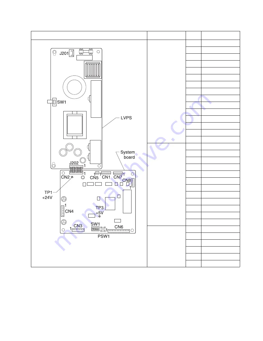
Connector locations

5-27


5061

CN6 Sensors
Side Door/Level/
Empty/
Registration 
Home/Pick Home

1

+5  V  dc

2

GND

3

SIDE

4

+5  V  dc

5

GND

6

LEVEL

7

+5  V  dc

8

GND

9

EMPTY

10

+5 V dc

11

GND

12

RHOME

13

+5 V dc

14

GND

15

PHOME

CN7 Size 
Sensors/Near 
Empty

1

+5  V  dc

2

GND

3

SIZE  0

4

+5  V  dc

5

GND

6

SIZE  1

7

+5  V  dc

8

GND

9

SIZE  2

10

+5 V dc

11

GND

12

NE EMP

CN8
S1(Pick Sensor)
S2(Registration 
Sensor)

1

+5  V  dc

2

S2

3

GND

4

+5  V  dc

5

S1

6

GND

Connector

Pin Signal

Содержание C77X

Страница 1: ...061 Table of Contents Start Diagnostics Safety and Notices Trademarks Index Lexmark and Lexmark with diamond design are trademarks of Lexmark International Inc registered in the United States and or o...

Страница 2: ...ication to products programs or services do not imply that the manufacturer intends to make these available in all countries in which it operates Any reference to a product program or service is not i...

Страница 3: ...ase printer 2 3 Symptom table 500 sheet drawer option 2 4 Symptom table HCIT 2000 sheet option 2 5 Symptom table output expander option 2 5 Symptom table 5 bin mailbox option 2 5 Symptom table StapleS...

Страница 4: ...2 56 927 03 error code service check 2 57 930 09 error code service check 2 57 940 xx error code service check 2 58 941 xx error code service check 2 60 942 xx error code service check 2 62 943 xx er...

Страница 5: ...enus and messages 2 119 Understanding the printer operator panel 2 119 Operator panel buttons 2 119 Menu map 2 121 Selected menus 2 122 Quality Menu 2 122 Utilities Menu 2 124 User attendance messages...

Страница 6: ...3 26 Serial Number 3 27 Engine Setting x 3 27 Model Name 3 27 Configuration ID 3 27 Reset Color Calibration 3 28 Edge to Edge 3 28 Cal Ref Adj 3 28 EP SETUP 3 28 EP Defaults 3 28 Fuser Temp 3 28 DC C...

Страница 7: ...panel bezel removal 4 7 Lens removal 4 9 Front cover rear pivot cover removal 4 10 Front cover or front cover backplate assembly removal 4 11 Redrive cap removal 4 12 Top cover assembly removal 4 13...

Страница 8: ...r removal 4 84 Rib housing removal 4 85 RIP fan removal 4 87 S2 narrow media transparency multipurpose feeder cable removal 4 88 S2 narrow media transparency multipurpose feeder sensors removal 4 89 S...

Страница 9: ...13 500 Sheet integrated tray 7 20 Assembly 14 Autocompensator assembly 7 21 Assembly 15 ITU assembly 7 22 Assembly 16 ITU drive assembly 7 23 Assembly 17 ITU loading 7 24 Assembly 18 Waste toner 7 26...

Страница 10: ...ty Pages Page 2 total of five B 3 Print Quality Pages Page 3 total of five B 4 Print Quality Pages Page 4 total of five B 5 Registration and alignment B 6 Quick Test Page B 6 Printhead mechanical alig...

Страница 11: ...r bei ordnungsgem er Wartung durch den Kundendienst Laserbestrahlung die Klasse I bersteigen w rde Menschen keinesfalls erreicht Avis relatif l utilisation de laser Pour les Etats Unis cette imprimant...

Страница 12: ...t ssio de 5 milliwatts operando numa faixa de comprimento de onda entre 770 e 795 nan metros O sistema e a impressora laser foram concebidos de forma a nunca existir qualquer possiblidade de acesso hu...

Страница 13: ...aessa olet alttiina n kym tt m lle lasers teilylle l katso s teeseen VARNING Osynlig laserstr lning n r denna del r ppnad och sp rren r urkopplad Betrakta ej str len Laser notis Denna skrivare r i USA...

Страница 14: ...0825 1 Els productes l ser de classe I no es consideren perillosos Aquesta impressora cont un l ser de classe IIIb 3b d arseni r de gal li nominalment de 5 mil liwats i funciona a la regi de longitud...

Страница 15: ...Notices and safety information xv 5061...

Страница 16: ...xvi Service Manual 5061...

Страница 17: ...ignes d entretien et de r paration de ce produit s adressent uniquement un personnel de maintenance qualifi Le d montage et l entretien de ce produit pouvant pr senter certains risques lectriques le p...

Страница 18: ...sobre el mantenimiento de este producto est dirigida exclusivamente al personal cualificado de mantenimiento Existe mayor riesgo de descarga el ctrica y de da os personales durante el desmontaje y la...

Страница 19: ...ducte est orientada exclusivament a professionals i no est destinada a ning que no ho sigui El risc de xoc el ctric i de danys personals pot augmentar durant el proc s de desmuntatge i de servei d aqu...

Страница 20: ...Connector locations uses illustrations to identify the connector locations and test points on the printer 6 Preventive maintenance contains the lubrication specifications and recommendations to preve...

Страница 21: ...ON A caution identifies something that might cause a servicer harm CAUTION This type of caution indicates there is a danger from hazardous voltage in the area of the product where you are working Unpl...

Страница 22: ...xxii Service Manual 5061...

Страница 23: ...thernet Token Ring LocalTalk serial infrared or additional parallel ports The printer has flexible paper handling It supports a wide variety of paper sizes and has a standard multipurpose feeder that...

Страница 24: ...to offer five output destinations in one option Each of the five bins supports approximately 100 pages of 20 lb 75 g m2 paper Only one output option above the printer is supported StapleSmart Finisher...

Страница 25: ...able settings to balance print darkness and toner savings The higher the setting the darker the print The toner darkness default setting is 4 Color level 4 and level 5 are the same The toner darkness...

Страница 26: ...in 604 5 mm 2 181 lb 82 3 kg Options 500 sheet drawer 5 in 127 mm 23 8 in 604 5 mm 18 5 in 469 9 mm 13 5 lb 6 1 kg 500 sheet tray 3 8 in 96 5 mm 15 6 in 396 2 mm 15 5 in 386 1 mm 2 6 lb 1 2 kg Duplex...

Страница 27: ...c extreme Operating clearances Printing states Lexmark C77x n Lexmark C77xdn Lexmark C78x n Lexmark C78xdn Printing average power W Base model 500 500 675 675 All options 540 540 675 675 Idle average...

Страница 28: ...Pa Ambient operating environment Temperature 60 to 90 F 15 6 to 32 2 C Relative humidity 8 to 80 Storage and shipping packaged printer with or without print cartridge Temperature 40 to 110 F 40 to 43...

Страница 29: ...irst copy time is defined as the elapsed time from pressing Enter on the keyboard to the page exiting to the output bin All tests pick paper from the primary input tray and the page exits into the pri...

Страница 30: ...ts may occur if an attempt is made to operate the printer with memory other than SDRAM DIMM memory with the stated specifications Flash Memory Options available are 32MB and 64MB Expansion Memory slot...

Страница 31: ...or only one with a 2000 sheet drawer 1 2000 Sheet drawer1 maximum of one Envelope drawer maximum of 3 or only one with a 2000 sheet drawer Outdoor media drawer Banner tray Maximum additional drawers M...

Страница 32: ...a duplex unit must be a 500 sheet drawer Media sizes and support Legend 3 supported with size sensing supported without size sensing 8 unsupported Media size Dimensions 500 sheet trays Multi purpose...

Страница 33: ...8 3 8 8 8 8 8 10 Envelope 104 8 x 241 3 mm 4 12 x 9 5 in 8 8 8 3 8 8 8 8 8 DL Envelope 110 x 220 mm 4 33 x 8 66 in 8 8 8 3 8 8 8 8 8 C5 Envelope 162 x 229 mm 6 38 x 9 01 in 8 8 8 3 8 8 8 8 8 B5 Envelo...

Страница 34: ...onal high capacity feeder Optional duplex Optional envelope drawer Optional banner tray Optional 5 bin mailbox Optional Finisher Standard Offset Staple Paper 3 3 3 3 8 8 3 3 3 3 Card stock 3 3 8 3 8 8...

Страница 35: ...lb Not recommended Not supported Tag 203 g m2 125 lb 203 g m2 125 lb Not supported Not supported Cover 216 g m2 80 lb 216 g m2 80 lb Not supported Not supported Transparencies8 Laser printer 161 to 1...

Страница 36: ...g m2 47 lb bond grain short is recommended 2 Paper weighing less than 75 g m2 20 lb bond is limited to simplex printing only at less than 60 relative humidity 3 Pressure sensitive area must enter the...

Страница 37: ...rd stock maximum grain short 1 Index Bristol 199 g m2 110 lb Not supported 199 g m2 110 lb 199 g m2 110 lb Not supported Tag 203 g m2 125 lb Not supported 203 g m2 125 lb 203 g m2 125 lb Not supported...

Страница 38: ...Staple 1 For 60 to 176 g m2 16 to 47 lb bond paper grain long fibers are recommended For papers heavier than 176 g m2 47 lb bond grain short is recommended 2 Paper weighing less than 75 g m2 20 lb bo...

Страница 39: ...Sulfite wood free or up to 100 cotton bonds 60 to 105 g m2 16 to 28 lb bond Not supported Not supported Not supported Not supported Media types and weights output options continued Media Type Media w...

Страница 40: ...hness The degree of smoothness of paper directly affects print quality If the paper is too rough the toner does not fuse to the paper properly resulting in poor print quality If the paper is too smoot...

Страница 41: ...aving a weight less than 60 g m2 16 lb Multiple part forms or documents Selecting paper Proper paper loading helps prevent jams and ensures trouble free printing To help avoid jams or poor print quali...

Страница 42: ...out sacrificing fuser life Web oiler fuser life 120 000 C78x models 200 000 C77x models Web oiler life 100 000 pages Availability Order the web oiler upgrade kit Upgrade kit This kit allows you to upg...

Страница 43: ...imulated Emission of Radiation LCD Liquid Crystal Display LED Light Emitting Diode LVPS Low Voltage Power Supply M Magenta MROM Masked Read Only Memory MS Microswitch NVRAM Nonvolatile Random Access M...

Страница 44: ...1 22 Service Manual 5061...

Страница 45: ...vice errors on page 2 11 User attendance messages on page 2 126 Service checks on page 2 14 for individual error messages Additional information can be found at the following locations Understanding t...

Страница 46: ...as been installed The printer detects at power on when the cover is closed that a new or different ITU has been installed The printer detects at power on that the fuser temperature is below 60 C When...

Страница 47: ...n page 2 116 Operator panel One or more buttons do not work Go to Operator panel LCD status LED buttons service check on page 2 90 Operator panel Display is blank printer does not sound 5 beeps but pr...

Страница 48: ...rint quality Light lines or streaks appear on the printed page Go to Light lines or streaks appear on the page on page 2 105 Print quality Light print Go to Light print over the entire page on page 2...

Страница 49: ...not recognize the correct media size Go to HCIT 2000 sheet option does not recognize the size paper selected on page 2 89 Paper jams in the HCIT Go to 2xx paper jams on page 2 9 Paper jams in the HCI...

Страница 50: ...displayed Unable to clear or reset message POST incomplete Go to Close Finisher Top Cover displayed unable to clear or reset message POST incomplete on page 2 113 Close Finisher Side Cover displayed U...

Страница 51: ...rinthead before performing checks in Printhead diagnostics on page 3 1 108 xx Printhead Error Yellow printhead error Check for the correct installation of all the cables to the system board assembly a...

Страница 52: ...or code service check on page 2 22 140 xx Motor Autocompensator motor error replace the autocompensator motor See Autocompensator pick assembly removal on page 4 27 If this does not fix the problem re...

Страница 53: ...er Jam Removal Door to access the jammed media If removing the jammed media does not fix the problem go to 200 07 paper jam service check on page 2 31 200 16 Paper Jam Clear Paper Path S2 sensor was m...

Страница 54: ...2 35 202 xx Paper Jam Clear Paper Path Media has jammed at the fuser Open the printer right door to access the jam area If removing the jammed media does not fix the problem go to 201 xx and 202 xx pa...

Страница 55: ...ing normal stapler operation such as when printing and stapling jobs Check stapler are for jam in accumulator or stapler Remove stapler cartridge to check for staple jam Press to initiate priming and...

Страница 56: ...failure replace the media size sensing board See Media size sensing board removal on page 4 58 952 xx NVRAM Failure NVRAM chip failure POR the printer 953 xx NVRAM Failure NVRAM chip failure operator...

Страница 57: ...the card in the specified slot 976 xx Standard Network Unrecoverable software or error in network for network card x If unable to clear the error message check the following If installed check network...

Страница 58: ...Due to memory restrictions the buffer is not saved during POR This means if a printer posts a 100 02 ITU Error so the belt is tracked off and the customer or servicer turns off the printer to clear th...

Страница 59: ...Go to step 5 5 Remove the ITU assembly and check that the sensor cable is seated in the handle of the ITU assembly correctly Note The sensor connector is located on the side of the ITU handle assembl...

Страница 60: ...rface Is the printer setting on a solid flat surface Go to step 11 Place the printer on a solid flat surface 11 Make sure the ITU drive motor assembly cable is correctly installed to the ITU drive mot...

Страница 61: ...rinter posts a 100 02 ITU Error so the belt is tracked off and the customer or servicer turns off the printer to clear the error when the printer starts up it will still not see the belt signal and wi...

Страница 62: ...surements as shown The lower limit is 3 1 mm the high limit is 8 1 mm and the optimum position is 5 6 mm Has the ITU Belt shifted to the front or to the rear Replace the ITU assembly See ITU assembly...

Страница 63: ...sembly See LVPS assembly removal on page 4 53 2 Turn the printer on and measure the voltage on connector J17 11 on the system board The voltage should measure approximately 0 13 V dc to 0 64 V dc as t...

Страница 64: ...blem replace the fuser assembly See Fuser assembly removal on page 4 44 4 Reinstall the fuser assembly Watch to see if the lamps turn on and off as the lamp heats up Do the lamps turn on Go to step 5...

Страница 65: ...correctly Is the hot roll lamp installed correctly Go to step 4 Install the lamp correctly If this does not fix the problem replace the fuser assembly See Fuser assembly removal on page 4 44 4 Reinsta...

Страница 66: ...ve the fuser from the printer Measure the voltage at the DC fuser control connector on the LVPS on pin 2 and 9 on the connector The voltage should measure approximately 5 V dc Is the voltage correct R...

Страница 67: ...led correctly Is the hot roll lamp installed correctly Go to step 4 Install the lamp correctly If this does not fix the problem replace the fuser assembly See Fuser assembly removal on page 4 44 4 Rei...

Страница 68: ...ly from the printer Measure the voltage on connector J17 6 on the system board The voltage should measure approximately 3 3 V dc Is the voltage correct Go to step 2 Replace the system board See System...

Страница 69: ...tor cable Do you measure continuity Go to step 4 Replace the ITU drive motor cable 4 ITU drive motor voltage check Measure the voltage on connector J16 on the system board The voltages are approximate...

Страница 70: ...Go to step 4 Replace the black cartridge assembly cable 4 Replace the black cartridge drive assembly Does this fix the problem Problem resolved Go to step 5 5 Replace the system board See System board...

Страница 71: ...ntinuity Go to step 4 Replace the cyan cartridge assembly cable 4 Replace the cyan cartridge drive assembly Does this fix the problem Problem resolved Go to step 5 5 Replace the system board See Syste...

Страница 72: ...motor removal on page 4 64 MPF motor sensor cable Replace the system board See System board removal on page 4 90 Step Actions and questions Yes No 1 Is sensor flag obstructed by paper debris out of p...

Страница 73: ...Check for obstructions in the paper path Is the paper path obstructed Clear the obstruction Go to step 4 4 Is the inner deflector out of position Correct the inner deflector position Go to step 5 5 If...

Страница 74: ...ng Edge guides should be adjusted against edge of media Media should be fanned and lay flat in the tray Is the media properly loaded in the tray Go to step 3 Properly load media 3 Remove the ITU and c...

Страница 75: ...Edge guides should be adjusted against edge of media Media should be fanned and lay flat in the tray Is the media properly loaded in the tray Go to step 3 Properly load media 3 Remove the ITU and chec...

Страница 76: ...S2 sensor 200 28 paper jam Is the sensor flag or sensor obstructed by paper debris Remove the paper or debris and go to step 2 Go to step 3 2 Replace the image transfer unit the cartridges and turn th...

Страница 77: ...m board removal on page 4 90 Step Actions and questions Yes No 1 Remove fuser from printer remove oiler housing from fuser and pivot the paper guide up Is paper jammed inside the fuser Clear the jam G...

Страница 78: ...t belts VTB for motion Observe the belt through the front door Are the belts on the VTB assembly turning Go to step 6 Go to Vacuum transport belt VTB removal on page 4 96 to verify correct installatio...

Страница 79: ...properly loaded in the tray Go to step 3 Properly load media 3 Remove the ITU and check for the jam at the second transfer roll Is paper jammed at the second transfer roll Clear the jam Contact your n...

Страница 80: ...e 4 26 6 Check for the proper operation of the redrive Are both belts in good condition and properly installed Go to step 7 Install or replace the redrive door See Redrive assembly removal on page 4 8...

Страница 81: ...etween the door and the metal plate Go to step 3 Replace the lower right door assembly See Lower right door assembly removal on page 4 24 3 Are any of the following conditions true Only the back of th...

Страница 82: ...t media loaded in Tray x does not meet media specifications 2 Make sure the media is loaded correctly Make sure the side and back restraints are located and seated properly Is the media loaded correct...

Страница 83: ...ly Replace the option or replace the following parts in the order until the error is cleared Autocompen sator pick assembly See Auto compensa tor pick assembly removal on page 4 27 Tray x system board...

Страница 84: ...ion by running the Tray x sensor test from the Diagnostics Menu See Sensor Test on page 3 20 Does the pass thru sensor operate correctly Check for any obstructions that might catch the media and creat...

Страница 85: ...t to observe paper feeding from the tray Does the paper feed from the paper tray Go to step 14 Go to step 4 4 Using the Standalone Feeding Operation Test observe the registration motor the registratio...

Страница 86: ...ration Test to determine where the paper jams Use the HCIT system board LED error code table on page 2 86 to help isolate problems in the feed unit assembly Are you able to determine where the failure...

Страница 87: ...Check to make sure the autocompensator pick rolls are correctly installed Are the autocompensator pick rolls correctly installed Go to step 6 Install the pick rolls correctly See Pick rolls removal o...

Страница 88: ...e both rolls at the same time Go to step 7 7 Check the pass thru sensor for correct operation by running the Tray x sensor test from the Diagnostics Menu See Sensor Test on page 3 20 Does the pass thr...

Страница 89: ...t to observe paper feeding from the tray Does the paper feed from the paper tray Go to step 14 Go to step 4 4 Using the Standalone Feeding Operation Test observe the registration motor the registratio...

Страница 90: ...system board Is the cable connected correctly Go to step 13 Install the cable correctly 13 Is the registration home sensor operating correctly Replace the following FRUs in the order shown 1 HCIT sys...

Страница 91: ...back restraints are located and seated properly Are the envelopes loaded correctly Go to step 3 Load the envelopes correctly 3 Observe if the envelopes feed from the tray Note You can observe the auto...

Страница 92: ...dalone Feeding Operation Test to observe paper feeding from the tray Does the paper feed from the paper tray Go to step 14 Go to step 4 4 Using the Standalone Feeding Operation Test observe the regist...

Страница 93: ...Replace the following FRUs in the order shown 1 Registration sensor 2 HCIT system board 14 Use the Standalone Feeding Operation Test to determine where the paper jams Use the HCIT system board LED er...

Страница 94: ...MPF assembly Go to step 2 10 Make sure that the MPF sensor cable from the system board is correctly installed at J10 on the system board Is the cable correctly installed Go to step 11 Install the cab...

Страница 95: ...ohms and 135 ohms Is the resistance correct Go to step 3 Replace the DC motor mechanical linkage assembly 3 DC motor mechanical linkage assembly Check for continuity between J4 1 and J4 2 and the cas...

Страница 96: ...control board 4 Bottom pass thru sensor voltage check 2 Check the voltage at J5 2 on the board the voltage measures approximately 0 V dc Is the voltage correct Replace the sensor assembly Replace the...

Страница 97: ...ics Menu See Finisher Feed Test on page 3 23 Go to step 2 2 Staple cartridge holder Check the staple cartridge holder for any signs of damage Did you find any damage to the staple cartridge holder Rep...

Страница 98: ...ves or option cards Does the 900 error persist when the printer is turned on Go to step 5 Determine which option is causing the 900 error 5 Restore factory defaults from the Configuration Menu Warning...

Страница 99: ...hese can be found on Print Menus page from the Utilities menu 4 Type of connection being used to print Record the type of connection For example direct USB or parallel or network peer to peer Ethernet...

Страница 100: ...check that it rotates freely Does the fan rotate freely Go to step 2 Replace the VTB fan See Vacuum transport belt VTB fan removal on page 4 98 2 Check the VTB fan cable connection to the system board...

Страница 101: ...RIP fan See RIP fan removal on page 4 87 Replace the system board See System board removal on page 4 90 Step Actions and questions Yes No 1 LVPS cable check the LVPS cable to J17 on the system board...

Страница 102: ...idge if there are no problems with the printer or if the cartridge is known to be defective Note Before proceeding with this service check observe the error log for repetitive occurrences of a 94x xx...

Страница 103: ...cracked or broken Go to step 6 Go to step 5 5 Check the mounting of the developer HVPS Make sure the screws that mount the power supply are properly tightened down and the board is positioned and moun...

Страница 104: ...measure approximately 3 3 V dc Go to step 10 Go to step 11 10 Check the developer HVPS to system board cable for damage broken connections or wire and shorts between adjacent pins Are there any signs...

Страница 105: ...cked or broken Go to step 6 Go to step 5 5 Check the mounting of the developer HVPS Make sure the screws that mount the power supply are properly tightened down and the board is positioned and mounted...

Страница 106: ...sure approximately 3 3 V dc Go to step 10 Go to step 11 10 Check the developer HVPS to system board cable for damage broken connections or wire and shorts between adjacent pins Are there any signs of...

Страница 107: ...broken Go to step 6 Go to step 5 5 Check the mounting of the developer HVPS Make sure the screws that mount the power supply are properly tightened down and the board is positioned and mounted correct...

Страница 108: ...measure approximately 3 3 V dc Go to step 10 Go to step 11 10 Check the developer HVPS to system board cable for damage broken connections or wire and shorts between adjacent pins Are there any signs...

Страница 109: ...roken Go to step 6 Go to step 5 5 Check the mounting of the developer HVPS Make sure the screws that mount the power supply are properly tightened down and the board is positioned and mounted correctl...

Страница 110: ...rd Turn on the printer Does the error continue Replace the system board See System board removal on page 4 90 Go to step 2 2 Replace each option board one at a time making sure the boards are properly...

Страница 111: ...tween 115 and 135 ohms Is the resistance correct Go to step 3 Replace the mechanical linkage DC motor assembly 3 DC motor Check between J2 1 and between J2 2 and the case of the DC motor for shorts Is...

Страница 112: ...d Replace the assembly that has the defective parts Replace the FRUs in the following order 1 Electronic size sensing assembly 2 Autocom pensator assembly 3 Drive Assembly Step Actions and questions Y...

Страница 113: ...cable at J4 and check the voltages at J4 on the board Warning Be careful not to short to adjacent pins on the connector The voltages measure approximately Are the voltages correct Replace the output e...

Страница 114: ...the bin selected 272 xx Paper Jam check bin 1 message on page 2 72 Go to step 8 8 990 Service Error Go to 950 xx Error Code service check Contact your next level of support Step Actions and questions...

Страница 115: ...nnected correctly Go to step 3 Install the sensor cable correctly 3 Bin x sensor flag Check the bin x sensor flag for binding and proper operation Are there any problems with the sensor flag Repair or...

Страница 116: ...ecto gater or deflector cover broken or binding shaft assemblies or broken gear teeth Are parts broken loose binding or missing Replace parts or repairs necessary Go to step 2 2 Bin x solenoid Check t...

Страница 117: ...20 installed correctly Go to step 4 Install the cable correctly and recheck 4 Autoconnect cables check the autoconnect from the printer or option above tray x Check for cuts pinched wiring or damage t...

Страница 118: ...ly 4 Check the following for loose broken or missing parts Boss on the side of the arm Bellcrank lift spring Tray interlock bellcrank Are any of these parts loose broken or missing Repair or replace a...

Страница 119: ...flag bellcrank Paper level sensing flag Paper level sensing flag spring Is the paper level sensing assembly installed correctly Replace the paper level sensing assembly Go to step 6 6 Make sure the pa...

Страница 120: ...and questions Yes No 1 Main AC power Make sure the printer is receiving main AC power Is the printer receiving AC power Go to step 2 Inform the customer that AC power to the printer is incorrect 2 AC...

Страница 121: ...stem board except JOPP1 J18 and J20 See System board on page 5 7 Does the printer power up and display a message Go to step 4 Replace the system board See System board removal on page 4 90 4 Turn off...

Страница 122: ...olls by opening the lower jam access door assembly Do the pick rolls turn Go to step 2 Go to step 3 2 Check the autocompensator pick rolls for contamination or damage to the rolls Is there any excessi...

Страница 123: ...from the printer Go to step 3 Go to step 2 2 Open the lower jam access door carefully lift the autocompensator assembly until it is in its uppermost position and carefully try to remove tray 1 Can you...

Страница 124: ...stallation and that the flag is not broken or damaged Is the paper level sensing assembly installed correctly and the flag not broken or damaged Go to step 5 Install correctly or replace the flag if d...

Страница 125: ...ates the switches correctly Is the actuator damaged or broken Replace the ITU assembly See ITU assembly removal on page 4 49 Go to step 3 3 Front cover assembly Does the front cover assembly close cor...

Страница 126: ...correctly or repair as necessary 5 Front cover assembly Make sure the front cover flag is not broken or damaged and actuates the switches correctly Is the flag broken or damaged Replace the front cove...

Страница 127: ...one of the option s that is installed beneath the printer Try to isolate which of the options is causing the problem Go to step 3 3 Make sure the duplex option is correctly installed Is the duplex op...

Страница 128: ...ption is installed correctly in the duplex frame Is the cable installed correctly Go to step 9 Correctly install the cable If the connector is damaged replace the cable assembly 9 Make sure the upper...

Страница 129: ...elope feeder installed correctly Go to step 4 Install the printer or options correctly and recheck performance 4 Check for the correct installation of the lower options autoconnect cable for the syste...

Страница 130: ...pes being used Has the tray been set up correctly Go to step 3 Set the tray up correctly 3 Check the tray for any signs of broken or damaged parts Are there any signs of damage to the tray or parts in...

Страница 131: ...board and check the voltages on connector J20 on the system board Note All voltages are approximate values Are the voltages correct Go to step 5 Replace the system board 5 Autoconnect cables Check th...

Страница 132: ...n solid or blinking On solid means that the HCIT has detected the front door or side door open Blinking means that the system is operating Is the LED on solid or blinking If the LED is on solid check...

Страница 133: ...ng media size sensor flag spring Is a sensor flag spring broken loose or missing Reconnect the spring if it is loose Replace the spring if broken or missing Go to step 5 5 Check the media size sensor...

Страница 134: ...tons fail to operate correctly Note If all the buttons fail to operate correctly the LCD display is blank power on status LED is on and the printer beeps 5 times go step B Replace the operator panel a...

Страница 135: ...rd removal on page 4 90 11 Operator panel cable Check continuity of the operator panel cable Is there continuity Replace the operator panel assembly See Operator panel assembly removal on page 4 68 Go...

Страница 136: ...standard bin even though bin x is selected Paper exits half way out of the redrive Go to 271 xx paper jam service check on page 2 51 Go to step 3 3 Remove paper Output Bin x is displayed POST is inco...

Страница 137: ...rol board to make sure they are attached securely and correctly Are the cables attached securely and correctly Go to step 4 Reseat the cables 4 Voltage check base printer autoconnect connector Turn th...

Страница 138: ...ontact your next level of support 3 Voltage Check the voltages at J5 3 and J5 4 The voltages should measure approximately 5 V dc Are the voltages correct Replace the sensor Replace the control board S...

Страница 139: ...ect printer driver for the installed software can cause print quality problems Incorrect characters could print and the copy may not fit the page correctly Note Some 201 xx Paper Jam errors can be cau...

Страница 140: ...and another color Does the color of the full bleed plane stay the same Replace the printhead see Printhead removal and adjustments on page 4 73 Replace the system board See System board removal on pag...

Страница 141: ...ny of the bellcranks broken Replace the broken bell cranks Go to step 3 3 Perform the partial print test See Partial Print Test on page 3 4 Is the image well developed on the PC drum but the same plan...

Страница 142: ...Go to step 8 Replace the cartridge contact assembly See Cartridge contact assembly removal on page 4 35 8 Perform a continuity check on the developer HVPS cable Does the cable check out Replace in or...

Страница 143: ...artridge Make sure the cartridge is seated properly and all packaging material is removed from the cartridge Has all packaging material been removed and the cartridge seated correctly Go to step 2 Rem...

Страница 144: ...by a cleaner problem in the print cartridge Are streaks magenta cyan or yellow Replace the cartridge Replace in order Black print cartridge ITU assembly See ITU assembly removal on page 4 49 Step Acti...

Страница 145: ...tion has not been disabled in the Diagnostics menus especially if the printer has been previously serviced Was color calibration disabled Set Color Calibration on Go to step 2 2 Toner density calibrat...

Страница 146: ...the quality of the transparency poor or do brown colors appear when projected Go to step 3 Go to step 4 3 Fuser settings From the Diagnostics menu select fuser settings and set to high Does this fuser...

Страница 147: ...rs have uneven print replace the ITU assembly The uneven print may appear as spots or streaks that are different on each page The most likely cause for this type of problem is damage to the ITU belt i...

Страница 148: ...d Replace the fuser assembly See Fuser assembly removal on page 4 44 Step Actions and questions Yes No 1 Remove the ITU assembly and check for any signs of debris near the paper feed reference edge me...

Страница 149: ...ITU assembly Replace the ITU assembly See ITU assembly removal on page 4 49 If only one color streaks in the printed area go to step 1 Step Actions and questions Yes No 1 Media settings Does the media...

Страница 150: ...igns of contamination on the lens of the printhead Is the printhead contaminated Go to Printhead removal and adjustments on page 4 73 Contact your next level of support Step Actions and questions Yes...

Страница 151: ...in Check the first transfer bellcranks and springs or replace the image transfer unit if the defects occur every 101 mm 4 in Replace the fuser if the defects occur every 148 mm 5 8 in Marks occur on e...

Страница 152: ...ng from another tray Replace the color print cartridge causing the streaks Print irregularities Paper has absorbed moisture due to high humidity You are using paper that does not meet the printer spec...

Страница 153: ...dark spots toner is smeared horizontal or vertical light bands appear or color does not project You are using transparencies that do not meet the printer specifications The Paper Type setting for the...

Страница 154: ...ions for the size loaded Incorrect margins Guides in the selected tray are set for a different size paper than what is loaded in the tray Auto size sensing is set to off but you loaded a different siz...

Страница 155: ...ment Change Paper Type Paper Texture and Paper Weight to match the paper or specialty media loaded in the printer Load paper from a fresh package Store paper in its original wrapper until you use it S...

Страница 156: ...hat is having transfer problems Is the cable disconnected or broken Reinstall or replace the cable Go to step 7 7 Transfer terminal contact assembly and ITU transfer bellcrank Check the transfer termi...

Страница 157: ...cables at J1A and J1B bottom autoconnect to the stapler card assembly to make sure they are attached securely Are the cables secure Go to step 2 Reconnect the cables securely 2 Check the voltages of t...

Страница 158: ...stapler option Does the side cover door actuate the switch when it closes Replace the stapler option Replace the stapler access door switch assembly Step Actions and questions Yes No 1 Left side bail...

Страница 159: ...drop 4 Check the stapler assembly for damaged or broken parts Check the flag and spring assembly on the front of the stapler assembly to see if the flag or spring are broken or missing Is the flag or...

Страница 160: ...ng broken or missing Replace the broken or missing flag or spring Go to step 2 2 Carefully cycle the large gear on the side of the stapler assembly and try to free the cartridge holder assembly Note L...

Страница 161: ...per tray guide damaged loose or missing Replace the paper tray guide Go to step 4 4 Check the following parts for wear damage or missing parts Wear strips Restraint pads Wear clip Side restraint Back...

Страница 162: ...he printer Is the tray correctly installed Go to step 2 Install tray 1 correctly If there is still a problem go to Tray 1 service check on page 2 117 2 Is another 500 sheet tray available Go to step 3...

Страница 163: ...o access the menu index A message indicating the menus are unavailable will appear if the printer is not ready Stop Press the Stop button to stop the mechanical operation of the printer After pressing...

Страница 164: ...t a host computer Numeric pad The numeric pad consists of numbers a pound sign and a backspace button The 5 button has a raised bump for non visual orientation The numbers are used to enter numeric va...

Страница 165: ...dge Black Cartridge Waste Toner Box Fuser ITU Reports Menu Settings Page Device Statistics Network Setup Page Wireless Setup Page Profiles List NetWare Setup Page Print Fonts Print Directory Print Dem...

Страница 166: ...is specified Customization is performed using the selections available under the Manual Color menu item Print Resolution Selects the quality of printed output 1200 dpi 4800 CQ default Toner Darkness L...

Страница 167: ...e Black Prints RGB samples using Display True Black color conversion tables Vivid Prints RGB samples using Vivid color conversion tables Off RGB No color conversion is implemented US CMYK Prints CMYK...

Страница 168: ...ting Color adjustment can be manually started by this operation No selections exist for this operation Pressing initiates this operation Enhance Fine Lines A selection to enable a print mode preferabl...

Страница 169: ...Prints a listing of all job statistics stored on the hard disk or clears all statistics on the disk Print Prints all statistics available for the most recent print jobs Clear Deletes all accumulated...

Страница 170: ...Use current to print on media currently in the printer Cancel the current job Change src Custom String Change src size Change src type size Check device Connection The specified device is either not f...

Страница 171: ...l displays the percent complete of the current phase Wait for the message to clear Enabling Menus Wait for the message to clear Encrypting Disk yyy DO NOT POWER OFF Warning Do not turn the printer off...

Страница 172: ...he Busy Waiting Menu Cancel Job Reset Printer Reset Active Bin Check Supply Levels Install duplex Invalid Engine Code Download valid engine code to the printer Note You can download engine code while...

Страница 173: ...es Wait for the message to clear Note The only supported file type is PDF Not ready The printer is offline Press to return to normal operation Overflow Bin Full The mailbox s designated overflow bin i...

Страница 174: ...emove the paper from all output bins Remove paper from linked set bin name The printer automatically senses media removal and resumes printing If removing the media does not clear the message press Re...

Страница 175: ...orted Remove the USB device to clear the message USB drive removed Wait for the message to clear Insert the USB drive USB hub unsupported Remove the USB device to clear the message View supplies Displ...

Страница 176: ...ustomer should install additional memory or set each link buffer to Auto Once all link buffers are returned to Auto you should exit the menu to activate the link buffer changes Once the printer return...

Страница 177: ...is displayed when the printer is processing an incoming job and there is not enough memory available to continue processing the job The following actions can be taken Determine how to make more memory...

Страница 178: ...nformatted flash detected Press to clear the message and continue printing You must format the flash memory before you can store any resources on it If the error message remains the flash memory may b...

Страница 179: ...cross a serial port but the port is disabled Note Once the error is displayed the first time reporting of further errors is suppressed until the printer is reset or menus are entered The following act...

Страница 180: ...is connected when it is not supported C770 More than one duplex unit is installed More than one option tray 500 sheet tray envelope feeder or outdoor media tray are connected above the HCIT The duplex...

Страница 181: ...clock position Undue pressure is not required to operate the lever Turn the printer off insert the ITU move the lever to the 6 o clock position and turn the printer back on If this does not resolve re...

Страница 182: ...2 138 Service Manual 5061...

Страница 183: ...Remove the top cover See Top cover assembly removal on page 4 13 2 Remove the outer system board shield See Outer system board shield removal on page 4 69 3 Verify that all the connectors are properl...

Страница 184: ...orded Note If an automatic calibration begins 36 Printer Service Required may appear Check the printhead cable connections Press to clear the error If the error code remains the same replace the syste...

Страница 185: ...ency of the defect locator chart go to the back of the hard copy service manual Note If you want to copy the chart then the following should be observed Since fax machines digital scanners and xerogra...

Страница 186: ...VTB through the access door and once again watch the test pages pass over the VTB 9 When the top half of the second page passes over the VTB quickly open the front cover assembly The printing stops 1...

Страница 187: ...inter mounted above the optional HCIT Note During normal operation the red LED on the HCIT system board blinks on for one second and off for one second Dip switch settings Do the following steps to se...

Страница 188: ...nd operations used while manufacturing and servicing the printer See Diagnostics mode on page 3 7 for more information Configuration Menu 1 Turn off the printer 2 Press and hold and 3 Turn on the prin...

Страница 189: ...N on page 3 10 Top Margin Bottom Margin Left Margin Right Margin Quick Test See Quick Test on page 3 11 ALIGNMENT See ALIGNMENT MENU on page 3 11 Cyan Yellow Magenta Factory Scanner Factory Manual Dri...

Страница 190: ...page 3 21 Sensor Test See Sensor Test on page 3 22 Diverter Test See Diverter Test on page 3 22 FINISHER TESTS Staple Test See Staple Test on page 3 23 Feed Test See Finisher Feed Test on page 3 23 S...

Страница 191: ...ee EP Defaults on page 3 28 Fuser Temp See Fuser Temp on page 3 28 DC Charge Adjust See DC Charge Adjustment on page 3 28 Dev Bias Adj See Dev Bias Adj on page 3 28 Transfer Adjust See Transfer Adjust...

Страница 192: ...age to expand or compress It is easier to adjust the Top and Left margins first then adjust the Bottom and Right 6 Press Select to save the value Submitting Selection appears 7 To verify the margin va...

Страница 193: ...ellow and magenta The black image should be aligned using REGISTRATION before the individual colors are aligned Setting alignment for color 1 Select ALIGNMENT MENU from the Diagnostics mode 2 Select C...

Страница 194: ...opriate thermistor cyan magenta yellow or black to make sure it is installed correctly to the system board and to the thermistor board If correct go to step b b Check the continuity of the appropriate...

Страница 195: ...isplay For example 3 To exit the test press any button Belt Tracking ITU 4th point adjustment This test is used to determine the need for the ITU Shim to correct 4th point alignment following the ITU...

Страница 196: ...within the Print Tests menu The content of the test page varies depending on the media installed in the selected input source If a source is selected that contains paper then a page similar to the Qu...

Страница 197: ...rom the menu Once the test is started it cannot be canceled When the test pages print the printer returns to the original screen HARDWARE TESTS LCD Test This test verifies the operator panel LCD funct...

Страница 198: ...aximum fail count being 99 999 Once the maximum pass count or fail count is reached the test stops the power indicator turns on solid and the final results appear If the test fails SDRAM Error appears...

Страница 199: ...However if the test fails one of the following messages appears for approximately three seconds Sync Busy Error Byte Interrupt Request Error Strobe Interrupt Request Error Init Fail Error Init Busy Er...

Страница 200: ...Each time the test finishes the screen updates with the result If the test passes the Pass Count increases by 1 However if the test fails one of the following failure messages appears for approximatel...

Страница 201: ...djustment is necessary the Top Margin in the Registration menu must be adjusted first The Duplex Top Margin Offset may be adjusted next A positive offset moves the text down the page and widens the to...

Страница 202: ...eeds one sheet of media from the selected source or Continuous continues to feed from the selected source until Back or Stop is pressed 4 Press Back or Stop to exit test Sensor Test This test can be u...

Страница 203: ...TESTS Feed Test Note If the Configure Bins printer setting is link rather than mailbox the printer selects its own internal bin linking regardless of which output bin is selected for the feed test Th...

Страница 204: ...s open Open displays 4 To exit the test press Back or Stop Diverter Test Note This test checks the operation of each mailbox output diverter Also if more than one 5 Bin mailbox option is installed the...

Страница 205: ...ee To run the Finisher Feed Test select Finisher Feed Test from the menu The printer feeds eight pieces of media to the finisher output bin This test cannot be canceled or terminated once the test has...

Страница 206: ...sors on page 5 3 for locations for these sensors See Cartridge contact assembly pin locations cyan magenta and yellow on page 5 4 or Cartridge contact assembly pin locations black on page 5 5 To run t...

Страница 207: ...ue with the test press Select If is selected Disk Test Clean BAD 000000 00 is displayed The screen updates periodically indicating the percentage of test completed and the number of bad blocks found 3...

Страница 208: ...ed 3 The left most digit blinks indicating it is the first digit to be changed To change the value press or until the desired value is displayed Press Select to move to the next digit The digit blinks...

Страница 209: ...h F Note When the printer detects a Configuration ID that is not defined or invalid the following occurs The default standard model Configuration ID is used instead Configuration ID is the only functi...

Страница 210: ...ore each of the printer settings contained in the EP Setup menu to their factory default value To restore the EP Setup settings to factory defaults select Restore To exit the menu without restoring th...

Страница 211: ...nt Log The history of printer errors can be printed The first page of the event log contains a Printer Information section similar to what is printed on a Menu Setting Page Printed at the top of each...

Страница 212: ...the Diagnostics mode 2 Select Yes to clear the Event Log or No to exit the Clear Log menu If Yes is selected the Empty Event Log displays on the screen 3 Press Back or Stop to exit the Clear Log menu...

Страница 213: ...mal mode Configuration Menu Reset Fuser Cnt See Reset Fuser Cnt on page 3 32 Black Only Mode See Black Only Mode on page 3 32 Prt Quality Pgs See Prt Quality Pgs on page 3 32 Color Trapping See Color...

Страница 214: ...d on A4 Legal or Letter paper 1 Select Prt Quality Pgs from the Config Menu 2 Press Select Go to Print tests on appendix page B 1 for representative samples of the pages Color Trapping Color trapping...

Страница 215: ...only available on models with an integrated network adapter In either case Restoring Factory Defaults is displayed after the operation is selected 1 Select Factory Defaults from the Config Menu 2 Sele...

Страница 216: ...of the user or the PJL command 1 Select Auto Color Adjust from the Config Menu 2 Select Off or a value from 100 to 1000 The default value is 500 Use to increase the value The values are in increments...

Страница 217: ...Settings are Delete and Do Not Delete default Disk Encryption This setting only appears if a hard disk is installed the disk is not read only and Disk Encryption is enabled Warning When the settings a...

Страница 218: ...the diagram Access doors and trays on page 3 36 for an overview of the paper path and areas where jams may occur The path varies depending on the paper source and output bins Access doors and trays Th...

Страница 219: ...r For instructions see Clearing fuser jams 230 xx Paper Jam duplex area E J Follow the instructions for clearing Area E and Area J 24 x xx Paper Jam trays 1 4 B C T x Follow the instructions for clear...

Страница 220: ...sure all printer covers doors and trays are closed and then press to resume printing Note The printer also displays x Pages Jammed Be sure to remove all the jammed pages before pressing Area A 1 If yo...

Страница 221: ...e the door Note Open Tray 1 and make sure the entire media stack is pushed all the way down into the tray Area C If you have one or more optional 500 sheet drawers 1 Open the 500 sheet drawer access d...

Страница 222: ...door Area D 1 Open the front access door 2 Hold down the front access door Remove jams in the rollers under the image transfer unit Note Any image printed will not be fused to the page Area T1 1 If c...

Страница 223: ...lex mechanism in the printer Area T x If you cannot clear all the 500 sheet drawer jams from Area C 1 Carefully open trays 2 through 4 all 500 sheet trays and remove jams Note Make sure the paper is p...

Страница 224: ...3 42 Service Manual 5061 Area J 1 Remove the duplex tray J 2 Remove any jams and then reinstall the tray Area K 1 Open the lower right access door 2 Remove any jams and then close the door...

Страница 225: ...per right access door 2 Remove jams from the rollers and then close the door Clearing mailbox finisher or output expander jams Area M 1 Open the rear door of the 5 bin mailbox or output expander 2 Pul...

Страница 226: ...2 2 Open both the upper right and the lower right access doors Areas K and L 3 Pull down the latches They slide toward the center to release the fuser 4 Pull the fuser out and set it on a clean flat s...

Страница 227: ...pull up to refasten them 11 Close the doors Clearing image transfer unit jams 1 Open the front access door and the left access door 2 While holding down the front access door insert a folded piece of...

Страница 228: ...n the front cover assembly 5 Remove all the print cartridges a Pull up slightly on the cartridge handhold b Pull the cartridge straight out and use the handle to lift it off the guides c Place the car...

Страница 229: ...ostic aids 3 47 5061 6 Release the latches to open the multipurpose feeder area A all the way 7 Remove the image transfer unit a Raise the lever to unlock the image transfer unit b Pull down on the ha...

Страница 230: ...urface Warning Do not touch the transfer belt Touching the belt will damage the image transfer unit 8 Look inside the printer Remove all torn paper or other jams 9 Insert the image transfer unit back...

Страница 231: ...Diagnostic aids 3 49 5061 b Rotate the handle up and push gently to lock the unit in place c Lower the lever to lock the image transfer unit into place...

Страница 232: ...rn the multipurpose feeder to its working position Reinstall all the print cartridges 11 Close the printer door 12 Turn the printer on The printer returns to a Ready state If you still need help Turn...

Страница 233: ...ricity in your body to the machine Hold the ESD sensitive part by its edge connector shroud cover do not touch its pins If you are removing a pluggable module use the correct tool Do not place the ESD...

Страница 234: ...connector to shield Attach 2 102 M3 5x8 mm Thread Cutting Cartridge guides to upper frame Attach 8 Upper front cover assembly to cartridge guides Attach 4 Front cover pivot to front upper cover Attach...

Страница 235: ...ches to lower right door Mounting 2 Bias latch cover to door Attach 1 MPF asm to MPF door Attach 6 Support bracket to MPF door Attach 4 MPF cable cover to door asm Mounting 1 MPF latch support bracket...

Страница 236: ...pper frame redrive Mounting 2 Developer HVPS to cartridge contact asm Mounting 4 BOR drive asm to upper frame Mounting 1 ITU drive asm to lower frame Mounting 3 Fuser drive asm to lower frame Mounting...

Страница 237: ...me Mounting 12 Upper door hinges to upper frame redrive Attach 2 Inner redrive assembly to upper frame Mounting 2 Paper level sensing assembly to lower frame Mounting 3 Inner deflector pick assembly t...

Страница 238: ...the electrical outlet before you connect or disconnect any cable or electronic board or assembly for personal safety and to prevent damage to the printer Disconnect any connections between the printe...

Страница 239: ...h overlays 1xx only Operator panel bezel with overlays 2xx only Operator panel bezel with overlays 3xx only or Operator panel bezel with overlays 4xx only on page 7 3 for the part number 1 Open the fr...

Страница 240: ...4 8 Service Manual 5061 4 Lift the bezel out and then straight up Note Be careful not to swing the bezel out too far and break off the clips Note Set the lens B aside It is not part of the bezel FRU...

Страница 241: ...Repair information 4 9 5061 Lens removal See Clear LCD lens on page 7 3 for the part number 1 Remove the bezel See Operator panel bezel removal on page 4 7 2 Remove the lens A...

Страница 242: ...cover rear pivot cover removal See Front cover rear pivot cover on page 7 3 for the part number 1 Remove the bezel See Operator panel bezel removal on page 4 7 2 Remove the four screws A 3 Remove the...

Страница 243: ...e front cover remove the front cover backplate and operator panel and reinstall on the new front cover See Front cover or Front cover backplate assembly on page 7 3 for the part numbers 1 Remove the f...

Страница 244: ...or panel See Operator panel assembly removal on page 4 68 Note Set aside the operator panel assembly and front cover backplate assembly for reinstallation The operator panel is not part of the front c...

Страница 245: ...art number 1 Remove the redrive cap See Redrive cap removal on page 4 12 2 Remove the front right light shield screw See Front right light shield removal on page 4 42 3 Remove the top cover screws A f...

Страница 246: ...4 14 Service Manual 5061 6 Remove the top cover mounting screws C from the front of the printer 7 Remove four screws D holding the outer system board shield 8 Remove the shield...

Страница 247: ...t the cable from J2 E on the system board 10 Lift the top cover and clip and remove the cable tie F 11 Pull the cable through the inner system board shield 12 Remove the autoconnect cable G from the c...

Страница 248: ...rnings Be sure the cables are in the cable retainer A Be sure the cables are not pinched by the top cover ribs against the indicated surfaces B of the printer frame Be sure to replace the cable tie C...

Страница 249: ...cover removal See Front lower left cover on page 7 3 for the part numbers 1 Remove the paper tray 2 Open the front cover assembly 3 Open the paper path access door carefully remove screw A type 323 o...

Страница 250: ...oor 5 Remove the screw D in the front left handle cover assembly 6 Remove the front lower left cover with the paper path door attached Paper path access door removal See Paper path access door on page...

Страница 251: ...ft cover See Front lower left cover removal on page 4 17 2 Remove the three front left handle cover assembly screws A type 323 on page 4 3 and remove the assembly Front lower right cover removal See F...

Страница 252: ...t jam access door B if tape is available to help hold the door in place The spring loaded latch is difficult to reassemble Avoid unlatching the left side if you just need access to the right screw 4 R...

Страница 253: ...nt right handle cover assembly on page 7 3 for the part number 1 Open the front cover assembly 2 Remove the toner cartridges 3 Remove the four front right handle cover assembly screws A type 323 on pa...

Страница 254: ...oval See Rear cover on page 7 5 for the part number 1 Remove the outer system board shield See Outer system board shield removal on page 4 69 2 Press the releases A to open the MPF all the way 3 Loose...

Страница 255: ...Repair information 4 23 5061 5 Remove 13 rear cover screws D and E 6 Remove tabs F from slots 7 Remove the rear cover E D D D E E F...

Страница 256: ...right cover See Front lower right cover removal on page 4 19 3 Loosen the two screws A 4 Remove the lower right door assembly Left lower cover removal See Left lower cover on page 7 5 for part number...

Страница 257: ...for the part number 1 Remove the paper path access door cover See Paper path access door removal on page 4 18 2 Remove the front left handle cover assembly See Front left handle cover assembly remova...

Страница 258: ...door removal See Redrive door assembly on page 7 14 for the part number 1 Open the redrive door 2 Loosen the redrive door upper hinge screw A type 324 on page 4 5 3 Lift the redrive door from the hin...

Страница 259: ...er 1 Remove the transfer plate assembly See Transfer plate assembly removal on page 4 95 2 Cut the cable tie A and remove the black mylar piece 3 Remove the front lower left cover See Front lower left...

Страница 260: ...belt The third screw is located at the rear pivot point for the transfer plate This allows the paper level assembly to drop into the integrated paper drawer b Disconnect the cable from the connector D...

Страница 261: ...Repair information 4 29 5061 6 Disconnect the pick motor connector E 7 Remove three screws F holding the pick assembly in place...

Страница 262: ...the pick arm to fall to the bottom of the tray 9 Disconnect the spring clip H from the pick arm Be sure not to let the spring come off of the lower frame Also identify which pegs the spring clip is s...

Страница 263: ...nter and drop it through the holes located next to the brackets Installation notes 1 Put the new pick assembly into the printer Make sure the pick motor connector is placed through the holes before yo...

Страница 264: ...tor pin B 3 Reattach the spring clip to the pick arm Make sure the pick arm rotates freely from top to bottom in the machine 4 Once the pick assembly is in place put the three screws for the pick asse...

Страница 265: ...he mylar piece and replace the cable tie Note When you place the mylar piece make sure you place it back under the metal bar C under the inner deflector Make sure that the blue cable running under the...

Страница 266: ...e front cover assembly 2 Remove the yellow toner cartridge 3 Remove the front right light shield cover See Front right light shield removal on page 4 42 4 Remove the BOR housing assembly screw A type...

Страница 267: ...e printheads 1 Open the front cover assembly 2 Remove the toner cartridges 3 Remove the ITU assembly See ITU assembly removal on page 4 49 4 Remove the top cover assembly See Top cover assembly remova...

Страница 268: ...4 36 Service Manual 5061 7 Press the cartridge contact assembly yellow shown retaining tabs B and remove the assembly 8 Remove the screw C from the front of the printhead B C...

Страница 269: ...Repair information 4 37 5061 9 Remove the screws D for the contact assembly you are removing Installation note Be sure to replace all the cable ties D...

Страница 270: ...hield removal on page 4 48 2 Remove the cartridge drive assembly mounting screws A Black is shown 3 Disconnect the cable B from the cartridge drive assembly 4 Note the location of the cable ties C and...

Страница 271: ...e 323 on page 4 3 and four bottom screws B type 121 on page 4 2 from the developer HVPS board 5 Remove the developer HVPS boards Installation notes Be sure to replace all the cable ties Install the la...

Страница 272: ...ler and buckler housing on page 7 19 for the part number 1 Open the MPF and press the releases A to open the MPF to the lowest position 2 Remove the MPF cable cover screw B 3 Release the MPF latch C a...

Страница 273: ...4 Use needlenose pliers to remove the buckler housing D Installation notes 1 Before installation insert the friction buckler into the buckler housing The tab E on the side should be aligned with the n...

Страница 274: ...ush with the edge Place the housing between the two sets of slots in the printer and then slide the housing into position Front right light shield removal See Front right light shield on page 7 3 for...

Страница 275: ...Repair information 4 43 5061 3 Unlatch the alignment stud C 4 Remove the front right light shield...

Страница 276: ...on page 7 7 for the part numbers 1 Turn the printer off Note The printer shouldbe powered down prior to removal and or replacement of the fuser 2 Open the lower right door assembly and redrive door C...

Страница 277: ...Reset Fuser counter in the Configuration Menu 1 Enter the Configuration Menu Turn off the printer turn on the printer while holding and release the buttons after about 10 seconds or when the clock fac...

Страница 278: ...47 3 Remove the redrive belt cover duct A 4 Remove fuser left duct B 5 Remove fuser bottom duct Fuser drive assembly removal See Fuser drive assembly on page 7 10 for the part number 1 Remove the fus...

Страница 279: ...age 4 22 2 Disconnect the fuser fan cable from connector JM1 A on the system board 3 Remove the fuser fan screws B and remove the fan Fuser top duct removal See Fuser top duct on page 7 5 for the part...

Страница 280: ...ve the rear cover See Rear cover removal on page 4 22 3 Remove the transfer HVPS board See Transfer HVPS board removal on page 4 92 4 Remove the system board See System board removal on page 4 90 5 Re...

Страница 281: ...1 ITU assembly removal See ITU assembly 1xx 3xx only on page 7 22 for the part number 1 Open the front cover assembly 2 Remove the toner cartridges 3 Open the MPF and press the releases A to open the...

Страница 282: ...4 50 Service Manual 5061 4 Raise the ITU release lever B 5 Slide the ITU assembly from the printer...

Страница 283: ...d closest to front 7 Slide the left side to the side to disengage from the gear and allow clearance to remove the roll Installation notes 1 Replace the second transfer roll 2 Be sure to replace the IT...

Страница 284: ...ive assembly removal on page 4 38 3 Disconnect the ITU drive coupling cable A 4 Cut the two cable ties B 5 Disconnect the ITU drive motor cable C 6 Remove the three ITU drive assembly mounting screws...

Страница 285: ...he geographic area you are in 1 Remove the fuser drive assembly See Fuser drive assembly removal on page 4 46 2 Remove the rear cover See Rear cover removal on page 4 22 3 Disconnect the J17 and J18 c...

Страница 286: ...4 54 Service Manual 5061 6 Remove the screw C type 121 on page 4 2 from the top of the LVPS and remove the LVPS from the printer...

Страница 287: ...conds or until the clock face appears 2 Print the Quick Test Page if possible Retain this sheet to verify the installation a Select REGISTRATION b Press Select to print the page 3 Turn the printer off...

Страница 288: ...w C from the media size sensing assembly 8 Gently twist and remove the media size sensing assembly As shown the assembly touches at the spring D the fingers E the bottom F and the right side G This al...

Страница 289: ...igning hole Be careful with the exposed fingers Do not allow them to press against the black plastic frame 3 Gently wiggle the entire assembly and press in and around the corner to the right 4 Grasp t...

Страница 290: ...sembly Also order cable tie parts packet P N 40X1648 on page 7 16 for the part number 1 Remove the rear cover See Rear cover removal on page 4 22 2 Disconnect the cables A 3 Remove the media size sens...

Страница 291: ...4 59 5061 Multipurpose feeder MPF removal See Multipurpose feeder MPF on page 7 19 for the part numbers 1 Open the MPF and press the releases A to open the MPF to the lowest position 2 Remove the MPF...

Страница 292: ...anual 5061 3 Remove the three screws C that secure the MPF inner cover 4 Press the latches D to release the MPF switch cable from the MPF sensor and disconnect the cable 5 Remove the cable from the ca...

Страница 293: ...Repair information 4 61 5061 6 Release the MPF latch F and remove the MPF...

Страница 294: ...F autocompensator or side restraints removal See MPF autocompensator pick assembly or MPF side restraint on page 7 19 for the part numbers 1 Remove the MPF See Multipurpose feeder MPF removal on page...

Страница 295: ...Repair information 4 63 5061 4 Unhook the autocompensator spring C 5 Rotate the shaft up and out of the MPF assembly...

Страница 296: ...n page 4 59 2 Remove the MPF autocompensators 1 and 2 See Multipurpose feeder MPF autocompensator or side restraints removal on page 4 62 3 Remove the four screws A to secure the MPF inner cover 4 Dis...

Страница 297: ...andle See Left lower cover removal on page 4 24 2 Remove waste toner container 3 Reinsert paper tray into printer 4 Remove the broken pieces of old handle a Pull up the upper piece of handle to raise...

Страница 298: ...y the nip relief lever B toward the rear of the printer and insert lower portion of the handle so that it is between the nip relief lever and the reference edge plate C 3 Holding the handle in place u...

Страница 299: ...onto the post press the upper portion of the handle to the right and rotate the handle into its home position This seats the nip relief lever into the correct position 5 Check for proper operation 6 I...

Страница 300: ...cover and front cover backplate assembly See Front cover or front cover backplate assembly removal on page 4 11 2 Remove the four screws A attaching the operator panel to the front cover 3 Remove the...

Страница 301: ...Repair information 4 69 5061 Outer system board shield removal See System board outer shield on page 7 33 for the part number 1 Remove four screws A 2 Remove outer system board shield...

Страница 302: ...ll the pick assembly down into the bottom pan and remove the screw Note Do not attempt to remove either the shaft or the clutch races Installation notes for the front roll When you replace the front r...

Страница 303: ...Reach around and depress the latch A on the end of the shaft and remove the roll Installation note for the rear roll When replacing both the front and back rolls note the directional markings on the r...

Страница 304: ...ing 1 Reach through the lower jam access door opening and lift and hold the pick assembly in the proper position 2 Press the autocompensator release lever B to engage the spring Note A piece of paper...

Страница 305: ...lor printhead electronic alignment on page 4 79 Do not loosen or replace more than one printhead at a time to retain factory settings The printhead alignment assemblies must be removed once the mechan...

Страница 306: ...remove 4 Align the printhead alignment assembly locating pin A with the hole in the printer frame and the attachment screw B with the screw hole shown without the printhead for clarity The adjustment...

Страница 307: ...selected printhead 6 Screw the printhead alignment assembly to the printer frame 7 Finger tighten the adjustment screw until the end of the screw is pressing firmly against the mounting beam 8 Disconn...

Страница 308: ...assemblies in place Note Untwist the printhead motor cables before placing the printhead assembly into the printer 12 Install the new printhead assembly reconnect the printhead motor cable into the s...

Страница 309: ...used to determine the printhead alignment This page contains information for black K magenta M cyan C and yellow Y printheads c Look at the line pertaining to the color of printhead you are replacing...

Страница 310: ...agnostic Menu 2 Select Quick Test 3 Set the top bottom left and right margin in that order The margins are set when the tip of the triangle touches the edge of the page The print registration range is...

Страница 311: ...until A is within 1 from B then go to step 2 5 Adjust the Step 2 settings Follow Step 2 of the instructions on the Test pages The goal is to change the value until the Test page shows A and B are wit...

Страница 312: ...arts packet including the rear transfer bellcranks for yellow cyan and magenta 1 Power off the printer 2 Remove the four toner cartridges and leave the front door open 3 Remove the ITU assembly See IT...

Страница 313: ...the bellcrank down B and remove Be careful not to lose the contact spring C Installation note Replace the bellcranks by reversing the order of removal Note Test the color coverage by running the Prin...

Страница 314: ...ff the printer 2 Remove the four toner cartridges and leave the front door open 3 Remove the ITU assembly See ITU assembly removal on page 4 49 4 Check each of the rear bellcranks for cracks or breaka...

Страница 315: ...emoval Note Test the color coverage by running the Print Quality Pages in the Diagnostics or Configuration Menu Redrive assembly removal See Redrive assembly on page 7 14 for the part number 1 Remove...

Страница 316: ...otch in the redrive assembly with tab C Registration motor removal See page 7 17 for the part number for the registration motor assembly kit 1 Remove the inner system board shield See Inner system boa...

Страница 317: ...on page 7 19 for the part number 1 Open the MPF and press the releases A to open the MPF to the lowest position 2 Remove the MPF cable cover screw B 3 Release the MPF latch C and lower the MFP door d...

Страница 318: ...e the rib housing D that requires replacement Installation note The end of the rib housing that goes into the printer first has tabs flush with the edge Place the housing between the two sets of slots...

Страница 319: ...mm on page 7 35 for the part number 1 Remove the rear cover See Rear cover removal on page 4 22 2 Disconnect the rip fan cable from the system board at connector J3 3 Remove the front rip fan screw A...

Страница 320: ...ares with the sensor cable assembly through the frame 4 Route the new cable connector through the rectangular opening in the upper frame and out through the opening in the lower frame Note Guiding the...

Страница 321: ...ee S2 XPAR NMS MPF cable assembly with sensors on page 7 37 for the part number 1 Remove the rear cover See Rear cover removal on page 4 22 2 Open the MPF and press the releases A to open the MPF to t...

Страница 322: ...mponent listed above If this procedure is not followed the printer will be rendered inoperable Never replace two or more of the components listed above without a POR after installing each one or the p...

Страница 323: ...re fully connected Replace all cable ties To verify the input sources are recognized 1 On the operator panel at the Ready prompt select Paper Menu 2 Select Paper Source 3 Make sure all installed optio...

Страница 324: ...061 Transfer HVPS board removal See Transfer HVPS board on page 7 34 for the part number 1 Remove the rear cover See Rear cover removal on page 4 22 2 Remove screw A and the two screws B on the bottom...

Страница 325: ...Repair information 4 93 5061 3 Remove all connectors C 4 Remove the transfer HVPS board...

Страница 326: ...y HVPS on page 5 20 When installing the transfer HVPS board route the cable to the HVPS input connector at CN1 C over the cable to the yellow transfer contact D under the cable to the magenta transfer...

Страница 327: ...art number 1 Remove the ITU assembly See ITU assembly removal on page 4 49 2 Remove tray 1 3 Lifting and rotate the right edge of the transfer plate up to a 45 angle to release the transfer plate 4 Re...

Страница 328: ...t number 1 Remove the transfer plate assembly See Transfer plate assembly removal on page 4 95 2 Remove the fuser bottom duct See Fuser bottom duct removal on page 4 46 3 Remove the two front screws A...

Страница 329: ...4 97 5061 6 Rotate release lever on gear until the gear can be removed 7 Remove screw from ground wire 8 Remove vacuum belt transfer belt unit far enough to release ground wire from restraint clips an...

Страница 330: ...Remove the rear cover See Rear cover removal on page 4 22 2 Disconnect VTB fan from the system board 3 Remove VTB fan with a flatblade screwdriver Waste container door removal See Waste container doo...

Страница 331: ...tch Also order cable tie parts packet P N 40X1648 on page 7 26 for the part number 1 Remove the media size sensing assembly See Media size sensing assembly removal on page 4 55 2 Use a flatblade screw...

Страница 332: ...e two fuser latches A 4 Remove the fuser assembly 5 Open the front cover assembly 6 Remove the yellow print cartridge 7 Remove the front light shield See Front right light shield removal on page 4 42...

Страница 333: ...Repair information 4 101 5061 9 Remove screw B from the top front support bracket Swing bracket to the right 10 Remove the two screws C securing the web oiler motor assembly B C...

Страница 334: ...al 5061 11 Remove the web oiler fuser motor assembly Note To reinstall the web oiler fuser motor assembly use the alignment pins D to position the assembly in holes E 12 Remove the four screws F secur...

Страница 335: ...assembly in holes B and install the assembly 2 Secure the web oiler motor assembly with screws C 3 Install the web oiler card using screws 4 Plug web oiler cable D into web oiler card connector Note M...

Страница 336: ...4 104 Service Manual 5061 5 Plug web oiler drive assembly cable into cable connector E 6 Reinstall paper path access door 7 Align tabs on the front right light shield with the slots F on the frame...

Страница 337: ...t light shield up until alignment stud G and the screw hole H are aligned 9 Attach the new web oiler fuser housing J to new web oiler fuser 10 Insert the web oiler fuser assembly into the fuser assemb...

Страница 338: ...4 106 Service Manual 5061...

Страница 339: ...Connector locations 5 1 5061 5 Connector locations Locations Printer boards...

Страница 340: ...5 2 Service Manual 5061 Printer motors...

Страница 341: ...Connector locations 5 3 5061 Printer sensors...

Страница 342: ...5 4 Service Manual 5061 Cartridge contact assembly pin locations cyan magenta and yellow...

Страница 343: ...Connector locations 5 5 5061 Cartridge contact assembly pin locations black...

Страница 344: ...5 6 Service Manual 5061 System board cabling reference Refer to the System board wiring diagrams for additional details...

Страница 345: ...Connector locations 5 7 5061 Connectors System board...

Страница 346: ...ULL_IN J2 BOR lift motor 1 LIFT_OUT 24 V dc in standby 2 LIFT_OUT 24 V dc in standby J4 Operator panel USB 1 VBUS 2 D 3 D 4 Ground J6 Developer HVPS 1 CART_METER_K_IN 2 K_AC_BIAS_ENABLE active low 3 S...

Страница 347: ...N C 14 BELT_HOLE 2 15 5V_SWITCHED J10 S2 narrow media prism MPF sensor 1 Ground 2 5V dc S2 switched 3 NARROW_MEDIA_IN 4 PAPERPATH_S2_IN 5 5 V dc NM switched 6 Ground 7 Ground 8 5 V dc PRISM switched 9...

Страница 348: ...D 16 N C J14 Cover open switch 24V dc switched 1 24V To Cover Open Switch 2 24V dc Switched J15 Fuser stepper motor yellow BLDC motor 1 Y_ON_OUT 2 FUSER_ON_OUT Fuser current I0 3 5V dc Through fuse F8...

Страница 349: ...Ground 10 Ground 11 K_CLK_OUT 12 ITU_CLK_OUT 13 K_HALL_IN 14 ITU_HALL_IN 15 N C 16 N C J17 Fuser interface 1 EXIT_SENSOR_IN 2 FUSER_CAM_1_IN 3 Ground 4 OILER_ENC_A_IN 5 OILER_ENC_B_IN 6 HR_THERM_IN ho...

Страница 350: ...13 Ground 14 Ground 15 Ground 16 Ground J19 Magenta cyan BLDC motors 1 M_ON_OUT 2 C_ON_OUT 3 5V dc Through fuse F8 4 5V dc Through fuse F8 5 M_DIR_OUT 6 C_DIR_OUT 7 24V_M_AND_C Through fuse F5 8 24V_...

Страница 351: ...10 N C 11 Ground 12 WASTE_BTL_PRES 13 TRAY_SIZE_3 14 Ground 15 TRAY_SIZE_2 16 TRAY_SIZE_1 17 Ground 18 3 3 V dc Through fuse F13 19 MEM_DATA I C Data to Media Size Card 20 MEM_CLK I C Clock to Media...

Страница 352: ...und 13 C_LADJ 14 Y_LPWM 15 Ground 16 5 V dc through fuse F12 and safety switches at J10 17 C_LENA 18 Ground 19 C_THERMISTOR 20 Y_DATA 21 Ground 22 Y_DATA JHD1 Optional hard disk drive JM1 Fuser fan 1...

Страница 353: ...K_LPWM 10 M_LADJ 11 Ground 12 Ground 13 K_LADJ 14 M_LPWM 15 Ground 16 5 V dc through fuse F12 and safety switches at J10 17 K_LENA 18 Ground 19 K_THERMISTOR 20 M_DATA 21 Ground 22 M_DATA JMMC1 Printhe...

Страница 354: ...motor 1 FUSE24V 2 Ground 3 Ground 4 V_V5FUSE 5 M_MMSTART 6 M_HSYN S0S 7 M_MMLOCK 8 Ground 9 M_MMREF 10 N C JMPF1 MPF motor and sensor 1 5 V dc 2 MPF Enc 3 Ground 4 MPF_Mtr 5 MPF_Mtr 6 Ground 7 5 V dc...

Страница 355: ...d 9 AUTOCOMP_OUT1 24 V dc in standby 10 AUTOCOMP_OUT2 24 V dc in standby JUSB1 USB port G1 Ground 1 USB 5 V dc 2 USB D 3 USB D 4 Ground G2 Ground JWEB1 Web oiler motor 1 5 V dc through fuse F8 2 OILER...

Страница 356: ...rvice Manual 5061 Autoconnect top Connector Pin no Color Signal CN1 Autoconnect top 1 White 24 V dc 2 Black Ground 3 Yellow Printer RXD 4 Black Ground 5 N A NC 6 Red 5 V dc 7 Black Ground 8 Blue Print...

Страница 357: ...5 19 5061 Autoconnect bottom Connector Pin no Signal Signal CN1 Autoconnect bottom 1 White 24 V dc 2 Black Ground 3 Yellow Printer RXD 4 Black Ground 5 Brown STAGING_ENCODER 6 Red 5 V dc 7 Black Groun...

Страница 358: ...5 20 Service Manual 5061 Transfer high voltage power supply HVPS...

Страница 359: ...Txenable T102 Transformer HV Terminal I ITU 1 HV Transformer output to 2nd Transfer Roll Cable T201 Transformer HV Terminal K Black 1 HV Transformer Output Terminal to Black Transfer Cable T301 Trans...

Страница 360: ...1 Developer HVPS Input 1 24 V dc Return 2 24 V dc 3 Y Ctsense 4 Y Devpwm 5 Y TnrSense 6 C Devpwm 7 C CtSense 8 M Devpwm 9 C TnrSense 10 CYM Acenable 11 M CtSense 12 CYM Chgpwm 13 M TnrSense 14 K Chgpw...

Страница 361: ...V dc 3 5 V dc 4 5 V dc 5 24 V dc 6 24 V dc 7 24 V dc 8 3 3 V dc Sense 9 Ground 10 Ground 11 Ground 12 Ground 13 Ground 14 Ground 15 Ground 16 Ground LVPS to system board cable for fuser J17 1 FusExit...

Страница 362: ...Pin no Signal LVPS AC Fuser Connector 1 AC Load 1 2 AC Common 3 Ground 4 N C 5 AC Load 2x LVPS DC Fuser Control Connector 1 FusExitSen 2 BURCam1 3 N C 4 WebEncoderA 5 WebEncoderB 6 HRThermistor 7 BURT...

Страница 363: ...sensing board Connector Pin Signal J1 1 3 3V dc 2 EPROM Data 3 Ground 4 EPROM Clock J2 1 J3 1 Waste BTL Full 2 Ground 3 Waste BTL PRESENT SW4 4 Tray Size 1 SW3 5 Ground 6 Tray Size 2 SW2 7 Tray Size...

Страница 364: ...2 PRI RXD 3 PGND 4 PERON 5 SGND 6 PRI TXD CN2 LVPS 1 Poweron 2 5 V dc 3 SGND 4 PGND 5 PGND 6 PGND 7 24 V dc 8 24 V dc 9 24 V dc CN3 REG Motor 1 24 V dc 2 24 V dc 3 REG A 4 REG A 5 REG B 6 REG B 7 No C...

Страница 365: ...c 5 GND 6 LEVEL 7 5 V dc 8 GND 9 EMPTY 10 5 V dc 11 GND 12 RHOME 13 5 V dc 14 GND 15 PHOME CN7 Size Sensors Near Empty 1 5 V dc 2 GND 3 SIZE 0 4 5 V dc 5 GND 6 SIZE 1 7 5 V dc 8 GND 9 SIZE 2 10 5 V dc...

Страница 366: ...din 2 Ground 3 prtrxd 4 Ground 5 Ground J2 Feed motor 1 fdmtr1 2 fdmtr2 3 Ground 4 Ground 5 tachft 6 5Vptt J3 Stepper motor 1 stpmtr 2 stpmtr 3 stpmtr 4 stpmtr 5 crtprsnt 6 stplow 7 stpphomo 8 Ground...

Страница 367: ...mpty sensor 1 Ground 2 bnempty 3 5Vsnsr2 J10 Left side sensor board 1 Ground 2 full 3 NRFull 4 Ground J12 Pass thru sensor 1 Ground 2 psthruint 3 5Vptt J13 Cover open switch 1 5V dc 2 Ground 3 cvropin...

Страница 368: ...5 30 Service Manual 5061...

Страница 369: ...els indicating the fuser assembly needs to be replaced to maintain the print quality and reliability of the printer The parts are available as a maintenance kit with the following part numbers 83 ITU...

Страница 370: ...no 23 grease Approved equivalent Shell Darina 1 and grease P N 99A0394 to lubricate appropriate areas Use Nyogel type 774 to lubricate the Fuser Drive Assembly and Nyogel 744 to lubricate the ITU and...

Страница 371: ...the points identified A from the supplied packet 2 Rotate the motor housing B to distribute evenly ITU drive assembly 1 Apply a thin coating of Nyogel type 744 grease to the points identified A from t...

Страница 372: ...6 4 Service Manual 5061...

Страница 373: ...kit or pkg refers to the number of units packaged together and identified by the part number NS Not shown in the Asm Index column indicates that the part is procurable but is not pictured in the illu...

Страница 374: ...7 2 Service Manual 5061 Assembly 1 Covers 3 2 4 1 10 10 5 37 34 35 36 7 5 9 6 8 26 27 29 31 32 30 25 11 8 10 8 5 10 8 8 33 28 12 17 14 10 18 24 22 23 19 15 21 13 16 20...

Страница 375: ...40X1636 4 1 Rear hold down spring 18 40X1610 4 1 Front hold down bellcrank 19 40X1609 1 1 Detent link 20 40X1623 1 1 Front access door handle 21 40X1614 1 1 Front cover 22 40X1626 1 1 Operator panel...

Страница 376: ...7 4 Service Manual 5061 Assembly 1 1 Covers 3 7 2 2 2 10 6 4 8 1 2 5 2 2 2 2 2 13 14 2 12 BACK 15 9 11 18 20 16 17 FRONT 12 19...

Страница 377: ...8 40X1654 1 1 Left lower cover 9 40X1656 1 1 Waste container door 10 40X1647 1 1 Ground cable 11 40X1644 1 1 Rear cover 12 40X1643 2 2 Fuser latch slide 13 40X1645 2 2 Fuser latch slide spring 14 40X1...

Страница 378: ...61 Assembly 2 Cartridge mounting Asm Index Part number Units mach Units FRU Description 2 1 40X1663 4 1 Guide assembly left side 2 40X1664 4 1 Guide assembly right side 3 12 8 Screw type 102 parts pac...

Страница 379: ...3 1 40X1666 1 1 Fuser assembly 220 V 500W 1xx 3xx 1 40X1832 1 1 Fuser assembly 220 V 500W 2xx 4xx 1 40X1651 1 1 Fuser assembly 115 V 500W 1xx 3xx 1 40X1831 1 1 Fuser assembly 115 V 500W 2xx 4xx 1 40X1...

Страница 380: ...7 8 Service Manual 5061 Assembly 3 1 Fuser web oiler 1 3 2...

Страница 381: ...5061 Assembly 3 1 Fuser web oiler Asm Index Part number Units mach Units FRU Description 3 1 1 40X1674 1 1 Web oiler assembly 2 40X1670 1 1 Web oiler driver board assembly 3 40X1669 1 1 Web oiler ind...

Страница 382: ...7 10 Service Manual 5061 Assembly 4 Fuser drive Asm Index Part number Units mach Units FRU Description 4 1 4 1 Screws type 323 parts packet 40X1633 2 40X1661 1 1 Fuser drive assembly 2 1...

Страница 383: ...s catalog 7 11 5061 Assembly 5 Vacuum transport belt VTB assembly Asm Index Part number Units mach Units FRU Description 5 1 40X1660 1 1 Jam access spring 2 40X1677 1 1 Vacuum transport belt assembly...

Страница 384: ...7 12 Service Manual 5061 Assembly 6 Transfer Asm Index Part number Units mach Units FRU Description 6 1 40X1678 1 1 Second transfer roll 2 40X1679 1 1 Transfer plate assembly 2 1...

Страница 385: ...ds Asm Index Part number Units mach Units FRU Description 7 1 40X1778 4 1 Printhead assembly do not replace more than one printhead at a time Also order cable tie parts packet P N 40X1648 2 12 12 Scre...

Страница 386: ...e 2 40X1685 2 2 Upper door hinge 3 2 2 Screw type 312 322 412 423 parts packet 40X1691 4 40X1689 1 1 Redrive belt 300 T 5 40X1684 1 1 Redrive assembly 6 40X1690 1 1 Redrive door assembly 7 40X1687 1 1...

Страница 387: ...Parts catalog 7 15 5061 Assembly 9 Paper feed input Asm Index Part number Units mach Units FRU Description 9 1 40X1692 1 1 S2 XPAR NMS MPF cable assembly with sensors 1...

Страница 388: ...Media size sensing bracket Also order cable tie parts packet P N 40X1648 3 40X1697 4 4 Media size sensing spring Also order cable tie parts packet P N 40X1648 4 4 4 Screw type 232 parts packet 40X1676...

Страница 389: ...0X1701 1 1 Nip relief handle Also order cable tie parts packet P N 40X1648 2 40X1702 1 1 Registration motor assembly kit including also order cable tie parts packet P N 40X1648 Staging motor assembly...

Страница 390: ...7 18 Service Manual 5061 Assembly 12 Multipurpose feeder MPF 3 7 5 2 6 4 16 17 14 11 1 13 8 9 10 10 11 9 12 5 5 5 5 19 15 5 20 18...

Страница 391: ...1 1 MPF paper out flag 8 40X1852 1 1 Paper out sensor MPF 9 40X1715 2 2 MPF support bracket cover 10 40X1707 2 2 MPF support bracket spring 11 40X1717 2 1 MPF support bracket 12 40X1713 1 1 Frame bias...

Страница 392: ...et tray assembly 2 40X1720 1 1 Back restraint latch 3 40X1719 1 1 Back restraint 4 40X1723 1 1 Tray bias bellcrank assembly 5 1 1 Screw type 312 322 412 423 parts packet 40X1691 6 40X1725 1 1 Tray bia...

Страница 393: ...ank 3 40X1724 1 1 Pick assembly 500 tray 4 40X1734 1 1 Bellcrank lift spring 5 40X1732 1 1 Paper level sensing assembly 6 40X1731 1 1 Tray interlock bracket 7 40X1729 1 1 Sensor paper out low 8 1 1 Sc...

Страница 394: ...ndex Part number Units mach Units FRU Description 15 1 40X1739 1 1 ITU light shield assembly 2 40X0342 1 1 ITU assembly 1xx 3xx only 2 40X0343 1 1 ITU assembly 2xx 4xx only 3 40X1678 1 1 Second transf...

Страница 395: ...number Units mach Units FRU Description 1 40X1823 1 1 ITU drive assembly Also order cable tie parts packet P N 40X1648 2 40X1742 1 1 58 gear Also order cable tie parts packet P N 40X1648 3 3 3 Screw...

Страница 396: ...7 24 Service Manual 5061 Assembly 17 ITU loading 3 3 3 3 2 2 2 2 1 4 4 4 4 5 4 4 4 4 11 10 12 7 8 9 13 6 14 15 15 16 17 16 5...

Страница 397: ...loading 1xx 3xx magenta including Magenta BOR spring Rear V block guide Rear transfer bellcrank Front V block guide Front transfer bellcrank High voltage contact spring 7 40X1849 1 1 Parts packet ITU...

Страница 398: ...art number Units mach Units FRU Description 18 1 40X1756 1 1 Waste toner container 2 40X1755 1 1 Waste container latch spring Also order cable tie parts packet P N 40X1648 3 40X1754 1 1 Waste containe...

Страница 399: ...Parts catalog 7 27 5061 Assembly 19 BOR drive assembly Asm Index Part number Units mach Units FRU Description 19 1 40X1758 1 1 Lift BOR assembly 1...

Страница 400: ...h Units FRU Description 20 1 40X1762 4 1 Cartridge contact assembly complete Also order cable tie parts packet P N 40X1648 2 40X1636 4 1 Rear hold down spring Also order cable tie parts packet P N 40X...

Страница 401: ...rive assembly Asm Index Part number Units mach Units FRU Description 1 40X1824 4 1 Cartridge drive assembly one drive assembly per package Also order cable tie parts packet P N 40X1648 2 12 12 Screw t...

Страница 402: ...7 30 Service Manual 5061 Assembly 22 Electronics 3 3 3 2 1...

Страница 403: ...ntina 1 40X0301 1 1 Power cord set 8 ft straight Australia 1 40X1766 1 1 Power cord set 8 ft straight Bolivia Peru 1 40X1773 1 1 Power cord set 8 ft straight Botswana Lesotho Namibia South Africa 1 40...

Страница 404: ...7 32 Service Manual 5061 Assembly 22 1 Electronics 3 5 4 8 1 9 10 2 2 6 6 6 7 6 6...

Страница 405: ...t with clips 6 20 20 Screw type 232 parts packet 40X1676 7 40X1775 1 1 System board network 1xx 3xx only Also order cable tie parts packet P N 40X1648 7 40X1817 1 1 System board network 2xx 4xx only A...

Страница 406: ...board to frame 3 1 1 Screw type 324 parts packet 40X1635 TFR HVPS board to frame 4 40X1794 3 3 Standoff high voltage power supply developer board 5 8 8 Screw type 121 parts packet 40X1780 6 40X1795 1...

Страница 407: ...Units FRU Description 22 3 1 40X1800 1 1 VTB fan 60 mm 2 40X1796 1 1 VTB fan gap cover 3 40X1798 1 1 Fuser fan assembly 4 2 2 Screws parts packet 40X1797 fuser fan mounting 5 40X1799 1 1 RIP fan 92 mm...

Страница 408: ...7 36 Service Manual 5061 Assembly 23 Electronics cabling interconnections 1...

Страница 409: ...assembly 11 40X1828 1 1 Printhead assembly magenta mirror motor attached to magenta printhead 12 40X1805 1 1 Laser cable black magenta 13 40X1828 1 1 Printhead assembly black mirror motor attached to...

Страница 410: ...7 38 Service Manual 5061 Assembly 24 Electronics cabling interconnections 2...

Страница 411: ...Units FRU Description 24 1 40X1753 1 1 Black terminal contact assembly 2 40X1759 1 1 Cyan terminal contact assembly 3 40X1761 1 1 Yellow terminal contact assembly 4 40X1757 1 1 Magenta terminal conta...

Страница 412: ...Manual 5061 Assembly 25 Electronics cabling interconnections 3 Asm Index Part number Units mach Units FRU Description 25 1 40X1810 1 1 HVPS control cable developer 2 40X1762 4 1 Cartridge contact asse...

Страница 413: ...7 41 5061 Assembly 26 Electronics cabling interconnections 4 Asm Index Part number Units mach Units FRU Description 26 1 40X1811 1 1 Options bottom media size sensing cable assembly 2 40X1823 1 1 ITU...

Страница 414: ...7 42 Service Manual 5061 Assembly 27 Output expander 3 11 7 5 9 10 6 4 8 13 18 16 15 17 12 14 19 20 21 1 22 2 23 24...

Страница 415: ...packet 40X2011 8 40X1982 1 1 Output option card shield 9 40X2013 1 1 Output expander DC motor board 10 40X1984 1 1 Front control board cover 11 40X1992 1 1 Output expander tray 12 40X2014 1 1 Diverter...

Страница 416: ...7 44 Service Manual 5061 Assembly 27 1 Output expander 3 3 11 7 13 5 5 9 2 10 6 4 12 8 1 15 14 14 14...

Страница 417: ...attach bracket 5 4 4 Screw parts packet 40X1813 6 40X1985 1 1 Front cover 7 40X2002 1 1 160 gear belt 8 40X2003 1 1 Belt idler arm assembly 9 40X2005 1 1 Belt tensioner spring 10 40X2010 1 1 Output t...

Страница 418: ...7 46 Service Manual 5061 Assembly 28 5 Bin mailbox 11 7 13 5 9 12 8 23 28 21 31 26 24 29 22 32 27 25 30 10 33 1 2 4 34 3 3 6 8 10 35 18 16 15 17 14 19 20...

Страница 419: ...p tray 15 40X2043 1 1 5 bin mailbox assembly kit 16 40X2027 1 1 Bail attach bracket assembly 17 1 1 Bail order P N 40X2043 5 bin mailbox assembly kit 18 40X2035 5 1 Paper tray support 19 40X2042 5 1 P...

Страница 420: ...7 48 Service Manual 5061 Assembly 28 1 5 Bin mailbox 3 3 3 3 11 7 13 5 9 2 10 6 4 12 8 14 1 15...

Страница 421: ...ator cam 5 40X2060 4 1 Diverter actuator spring 6 40X2058 4 1 Diverter actuator latch 7 40X2059 4 1 Diverter actuator arbor 8 40X2069 4 1 C clip retainer 9 40X2021 1 1 Attach front bracket 10 40X2061...

Страница 422: ...7 50 Service Manual 5061 Assembly 29 500 Sheet drawer option 3 11 7 5 9 2 10 6 4 8 1...

Страница 423: ...on complete 2 40X1728 1 1 500 Sheet tray assembly 3 40X1720 1 1 Back restraint latch 4 40X1719 1 1 Back restraint 5 40X1723 1 1 Tray bias bellcrank assembly 6 1 1 Screw type 312 322 412 423 parts pack...

Страница 424: ...7 52 Service Manual 5061 Assembly 29 1 500 Sheet drawer option 3 11 7 13 17 15 9 2 2 2 2 2 2 2 2 2 2 2 2 2 10 16 4 12 8 14 18 1 19 20 21 5 6 16 16 16 22 23...

Страница 425: ...me cover 8 40X1730 1 1 Tray interlock bellcrank 9 40X1891 1 1 Pass thru sensor 10 40X1896 1 1 Hinge 11 40X1894 1 1 Electronics size sensing assembly with system board 12 40X1741 1 1 Pick arm lift bell...

Страница 426: ...7 54 Service Manual 5061 Assembly 30 Duplex option 2 3 5 6 4 8 7 9 11 10 12 13 14 17 18 19 20 21 22 23 24 25 26 27 28 16 29 15 1 5 5 5 5 5 5 5 5 5 3 3 3 30 16 16 16...

Страница 427: ...ket 11 40X1964 1 1 Sensor mount plate 12 40X1927 1 1 Duplex exit sensor 13 40X1924 1 1 Duplex shaft mount 14 40X1954 1 1 Front decurl assembly 15 40X1979 1 1 F R backup shaft assembly 16 40X1951 1 1 5...

Страница 428: ...7 56 Service Manual 5061 Assembly 30 1 Duplex option 1 2 3 4 7 5 5 5 5 5 20 6 13 12 10 14 6 8 14 16 19 9 12 13 15 17 18 21 11 11...

Страница 429: ...ck 7 40X1937 1 1 Back support 8 40X1922 1 1 Duplex card assembly 9 40X1958 1 1 Transfer belt 10 40X1960 1 1 Right jam clearance tray assembly 11 40X1969 1 1 C clip retainer 12 40X1953 2 1 Aligner spri...

Страница 430: ...7 58 Service Manual 5061 Assembly 31 High capacity input tray HCIT 1 2 3 4 5 6 7 8 30 31 29 28 28 28 28 28 27 27 26 25 24 6 6 6 9 9 21 22 22 23 32 33 9 36 34 37 35 11 10 12 9 9 13 15 14 16 17 18 19 20...

Страница 431: ...15 40X2115 1 1 Paper tray guide 16 40X2134 1 1 Elevator lift belt 17 40X2136 1 1 Elevator lift 18 40X2139 3 1 Ring 7 elevator lift gear elevator lift 19 40X2135 1 1 Elevator lift gear 20 40X2114 2 1 P...

Страница 432: ...7 60 Service Manual 5061 Assembly 31 1 High capacity input tray HCIT 1 2 6 3 7 11 8 8 4 4 5 5 3 9 10 12 4 4 4 4 13 14...

Страница 433: ...1 Caster fixed 9 40X2144 1 1 Left side cover 10 40X2146 1 1 Upper left side jam cover 11 40X2100 1 1 Locating pin options front right 12 40X2099 1 1 Locating pin options rear left 13 40X2106 1 1 Optio...

Страница 434: ...40X2155 1 1 Jam access door 4 40X2156 1 1 Front door latch 5 40X2157 1 1 Access door rear latch 6 40X2152 1 1 Front assembly cover 7 40X2153 1 1 Stapler access cover 8 40X3274 1 1 Stapler access door...

Страница 435: ...Parts catalog 7 63 5061 Assembly 32 1 StapleSmart finisher Asm Index Part number Units option Units FRU Description 32 1 1 40X3278 1 1 Stapler assembly 1...

Страница 436: ...Service Manual 5061 Assembly 32 2 StapleSmart finisher Asm Index Part number Units option Units FRU Description 32 2 1 40X3279 1 1 Switch assembly safety cover open 2 99A0104 1 1 Spring upper diverter...

Страница 437: ...Parts catalog 7 65 5061 Assembly 32 3 StapleSmart finisher Asm Index Part number Units option Units FRU Description 32 3 1 99A2480 1 1 StapleSmart wheels maintenance kit 1...

Страница 438: ...7 66 Service Manual 5061 Assembly 33 Envelope option 2 1...

Страница 439: ...7 67 5061 Assembly 33 Envelope option Asm Index Part number Units option Units FRU Description 33 1 40X1842 1 1 Envelope option complete 2 40X1843 1 1 Envelope tray assembly NS 40X2080 1 1 Envelope fe...

Страница 440: ...ervice Manual 5061 Assembly 34 Outdoor media tray option Asm Index Part number Units option Units FRU Description 35 1 40X2083 1 1 Outdoor media drawer assembly 2 40X2084 1 1 Outdoor media tray assemb...

Страница 441: ...ts catalog 7 69 5061 Assembly 35 Banner option Asm Index Part number Units option Units FRU Description 36 1 40X2086 1 1 Paper support bail 2 40X2088 1 1 Banner option screw 3 40X2087 1 1 Wire bail 2...

Страница 442: ...7 70 Service Manual 5061 Assembly 36 Options...

Страница 443: ...assembly 2xx 4xx only NS 40X4754 1 1 PRESCRIBE card assembly 2xx 4xx only NS 40X0291 1 1 Adapter parallel 1284 B NS 40X2610 1 1 Hard Disk 40GB with adapter formatted NS 40X1592 1 1 MarkNet N7020e ENA...

Страница 444: ...7 72 Service Manual 5061...

Страница 445: ...is necessary to perform the Mechanical alignment on page 4 73 the Black printhead electronic alignment on page 4 78 if necessary and the Color printhead electronic alignment on page 4 79 The front cov...

Страница 446: ...roller in these photos is only visible because the printer has been disassembled to the frame The gear will have to be located by feel to ensure proper installation Redrive gear A and auto tension ge...

Страница 447: ...deflector in the fuser and the paper is diverted away from the duplex The duplex option does not receive the sheet and prompts a 230 Paper Jam message Replace the rubber deflector button with the encl...

Страница 448: ...A 4 Service Manual 5061 3 Place the new button into the cam 4 Verify the new button moves freely by pressing the button firmly down and watching it snap back Note Leave the button in the up position...

Страница 449: ...e pages available in various menus While they are as close as possible to what you will see variations in printing may result from individual user printer settings media and printer alignment Print te...

Страница 450: ...B 2 Service Manual 5061 Print Quality Pages Page 1 total of five...

Страница 451: ...Appendix B Print quality samples B 3 5061 Print Quality Pages Page 2 total of five...

Страница 452: ...B 4 Service Manual 5061 Print Quality Pages Page 3 total of five...

Страница 453: ...Appendix B Print quality samples B 5 5061 Print Quality Pages Page 4 total of five...

Страница 454: ...B 6 Service Manual 5061 Registration and alignment Quick Test Page In Diagnostic Menu select REGISTRATION and select Quick Test...

Страница 455: ...Appendix B Print quality samples B 7 5061 Printhead mechanical alignment test page In Diagnostics Menu select MISC TESTS and select Printhead Inst...

Страница 456: ...B 8 Service Manual 5061 Printhead electronic alignment test page Magenta one of two In Diagnostic Menu select ALIGNMENT select a color and select Quick Test...

Страница 457: ...Appendix B Print quality samples B 9 5061 Printhead electronic alignment test page Magenta two of two...

Страница 458: ...B 10 Service Manual 5061...

Страница 459: ...onnections 5 18 B banner tray 7 69 BASE SENSOR TEST 3 24 Belt Tracking 3 13 Black Only Mode 3 32 BOR drive assembly location 5 2 parts catalog 7 27 removal 4 34 service checks 2 80 Button Test 3 15 bu...

Страница 460: ...g 3 30 Display Log 3 29 Print Log 3 29 EXIT DIAGNOSTICS 3 9 3 30 FINISHER TESTS 3 23 Finisher Feed Test 3 23 Finisher Sensor Test 3 23 Staple Test 3 23 HARDWARE TESTS 3 15 Button Test 3 15 CACHE Test...

Страница 461: ...assembly location 5 1 Fuser Temp 3 28 G guidelines media 1 17 H hard disk Disk Encryption 3 35 Jobs On Disk 3 35 HCIT standalone test mode 3 5 Hex Trace 2 125 high capacity input tray HCIT connections...

Страница 462: ...7 69 BOR drive assembly 7 27 cartridge contact assembly 7 28 cartridge drive assembly 7 29 cartridge mounting 7 6 covers 7 2 7 4 duplex option 7 54 7 56 electronics 7 30 7 32 7 34 7 35 electronics ca...

Страница 463: ...assembly 4 11 front cover rear pivot cover 4 10 front left handle cover assembly 4 19 front lower left cover 4 17 front lower right cover 4 19 front right handle cover assembly 4 21 left lower cover...

Страница 464: ...x option deflector button replacement 8 3 identifying system board cabling 5 6 identifying the printheads 8 1 redrive belt routing 8 2 setting printer alignment 3 11 SIZE SENSING 3 32 specifications a...

Страница 465: ...Index I 7 5061 waste container latch 7 26 waste toner container parts catalog 7 26 web oiler fuser location 5 1 removal 4 100 upgrade kit 1 20...

Страница 466: ...I 8 Service Manual 5061...

Страница 467: ...MM card assembly 7 71 40X1508 128MB SDRAM card assembly 7 33 7 71 40X1509 256MB SDRAM card assembly 7 33 7 71 40X1510 512MB SDRAM card assembly 7 33 7 71 40X1512 Japanese font card assembly 7 71 40X15...

Страница 468: ...de spring 7 5 40X1646 Duplex actuator arm assembly 7 5 40X1647 Ground cable 7 5 40X1648 Cable tie 6 in pack 7 5 7 53 7 57 40X1649 Cable tie mount 7 5 40X1650 Fuser left duct 7 5 40X1651 Fuser assembly...

Страница 469: ...ly 7 19 40X1717 MPF support bracket 7 19 40X1718 Side restraint 7 20 40X1719 Back restraint 7 20 7 51 40X1720 Back restraint latch 7 20 7 51 40X1722 Wear strip 7 20 7 51 40X1723 Tray bias bellcrank as...

Страница 470: ...led 7 33 40X1785 Ground cable 7 33 40X1786 Cable clip 7 33 40X1787 Jam access door spring 7 5 40X1791 Power cord set 8 ft Taiwan 7 31 40X1792 Power cord set 8 ft Korea 7 31 40X1793 Transfer HVPS board...

Страница 471: ...ensing assembly with system board 7 53 40X1895 500 sheet option spring 7 53 40X1896 Hinge 7 53 40X1897 Wall support plate 7 53 40X1898 Paper level sensing assembly 7 53 40X1899 Media size sensing asse...

Страница 472: ...7 43 40X1982 Output option card shield 7 43 40X1983 Rear attach bracket 7 45 40X1984 Front control board cover 7 43 40X1985 Front cover 7 45 40X1986 Rear cover 7 43 40X1987 Rear support cover 7 43 40X...

Страница 473: ...40X2047 Roller retainer 7 49 40X2049 Rear access door roller assembly 7 47 40X2050 Main DC drive assembly 7 47 40X2052 Lower autoconnect cable assembly 7 47 40X2053 Upper autoconnect cable assembly 7...

Страница 474: ...59 40X2125 Rear feed unit spring 7 59 40X2126 Plastic 5W clip 7 59 40X2127 Level sensor flag 7 59 40X2128 Near empty sensor flag 7 59 40X2129 Extension spring 7 59 40X2130 Tray present lever 7 61 40X2...

Страница 475: ...only 7 71 40X4268 Front door assembly 7 47 40X4741 Bar code card assembly 2xx 4xx only 7 33 7 71 40X4742 Lexmark Forms card assembly 2xx 4xx only 7 71 40X4743 IPDS SCS card assembly 2xx 4xx only 7 71...

Страница 476: ...I 18 Service Manual 5061...

Страница 477: ...d Transfer Roll 144 6 5 69 M to Second Transfer Roll 245 6 9 67 C to Second Transfer Roll 346 6 13 65 Y to Second Transfer Roll 447 6 17 62 Meter 1 to Second Transfer 164 8 6 49 Meter 2 to Second Tran...

Страница 478: ......

Страница 479: ......

Страница 480: ......

Отзывы: