Lex 2I847PW Скачать руководство пользователя страница 25

21

CHP2: 2x40 Pin 2.00mm Male

Description

APin Number

Pin Number

Description

VCC

A1

B1

DTR2

CTS2

A2

B2

TXD2

RTS2

A3

B3

RXD2

DSR2

A4

B4

DCD2

GND

A5

B5

GND

NC

A6

B6

NC

NC

A7

B7

NC

NC

A8

B8

NC

NC

A9

B9

NC

GND

A10

B10

GND

NC

A11

B11

NC

NC

A12

B12

NC

NC

A13

B13

NC

NC

A14

B14

NC

GND

A15

B15

GND

U

A16

B16

USB_P2_D-

U

A17

B17

USB_P3_D-

GND

A18

B18

GND

PS2 KB/MS VCC

A19

B19

USB_P23_VCC

KB_CLK

A20

B20

KB_DATA

MS_CLK

A21

B21

MS_DATA

GND

A22

B22

GND

POWER SWITCH

A23

B23

RESET SWITCH

SMB_DATA

A24

B24

POWER_LED_N

SMB_CLK

A25

B25

HDD_LED_N

+V3.3S

A26

B26

LAN_LED_N

GND

A27

B27

GND

PCIE_TX_P

A28

B28

PCIE_TX_N

PCIE_RX_P

A29

B29

PCIE_TX_N

PCIE_CLK_P

A30

B30

PCIE_CLK_N

GND

A31

B31

GND

GND

A32

B32

3.3V

U

A33

B33

USB_P4_D-

U

A34

B34

USB_P5_D-

USB3_P45_VCC

A35

B35

GND

GND

A36

B36

GND

USB3_TX_P

A37

B37

USB3_TX_N

GND

A38

B38

GND

USB3_RX_P

A39

B39

USB3_RX_N

GND

A40

B40

+V5S

Note: PIN A26, B40 offer 500mA. Do not use it to be power supply.

Содержание 2I847PW

Страница 1: ...Board 4GB DDR3 1333 MT s 2 x LAN 2 x HDMI USB 2 x COM 1 x VGA All In One Intel Mobile Ivy Bridge Celeron 1047UE 1 4GHz CPU i3 i7 processor VGA HDMI PCIe mini card PCIe 160 pin connector Multi LAN Boa...

Страница 2: ...S DATA SET 2 10 JSC1 JSC2 COM1 COM2 RS232 RS422 RS485 SELECT CHAPTER 3 CONNECTION 3 1 LIST OF CONNECTORS 3 2 2 x 40 PIN 2 00mm MALE 3 3 BATTERY INPUT 3 4 DC VOLTAGE OUTPUT 3 5 DIGITAL INPUT OUTPUT WAT...

Страница 3: ...8 1 PCH IO CONFIGURATION 4 8 1 1 PCI EXPRESS CONFIGURATION 4 8 1 1 1 MINI PCIe 1 2 4 8 1 2 USB CONFIGURATION 4 8 1 2 1 xHCI MODE 4 8 1 3 PCH AZALIA CONFIGURATION 4 8 2 SYSTEM AGENT SA CONFIGURATION 4...

Страница 4: ...eeps the rights in the subject to change the contents of this manual without prior notices in order to improve the function design performance quality and reliability The author assumes no responsibil...

Страница 5: ...ase deal with heat dissipation properly when buying single MB set 9 Please avoid approaching the heat sink area to prevent users from being scalded with fanless products 12 It is important to install...

Страница 6: ...U if you change modify any parts of the CPU cooler 6 Please wear wrist strap and attach it to a metal part of the system unit before handling a component You can also touch an object which is ground c...

Страница 7: ...3 2 1 3 1 2 3 Photo 1 Insert Unplug...

Страница 8: ...VI HDMI 1 3a This integrated platform offers superb performance and PC specification in the industry Despite the limited space of 2I847PW it supports 2 COM ports 1 port USB 3 0 and 5 ports of Hi Speed...

Страница 9: ...5 Support DX11 DX10 1 DX10 DX9 and OGL 3 0 6 Support two channel HD audio 7 Support 2 x COM ports 1 x USB3 0 and 5 x USB 2 0 8 Support extended 2 x Mini PCIe card 2 x full size 9 Support one SATA conn...

Страница 10: ...ss 80 pin connector B Power Wide Range DC IN 9 36V Display 1 x HDMI 1 x VGA USB 2 x USB 2 0 Audio Line out Mic in COM 1 x RS232 or RS422 or RS485 LAN 2 x Intel 10 100 1000 Mbps 5 SATA One SATA ports 3...

Страница 11: ...lling the Mini PCI e Card 1 Unfasten the round headed M2 6 screw for half size Mini PCI e 3 Fasten a round headed M2 6 screw 2 Install a mSATA card at the angle of 45 The half size Mini PCI e slot sup...

Страница 12: ...ling the 2I847PW for harmlessly discharge any static electricity through the strap 2 Please use anti static pad to put any components parts or tools on the pad whenever you work on them outside the co...

Страница 13: ...TO INSTALL THIS BOARD CONTACT THE DEALER YOU PURCHASED THIS BOARD FROM IMMEDIATELY 4 Check your optional parts i e DDR CF etc all necessary jumpers setting to jumper pin set and CMOS setup correctly P...

Страница 14: ...10 2 3 Dimension 2I847PW...

Страница 15: ...11 2 4 Layout 2I847PW CPH2 CPH1 JSC1 JSC2 CPO1 CO1 CIO1 CBAT1 JSB12 MPCE1 MPCE2 TOP...

Страница 16: ...12 2 4 1 Layout 2I847PW SATA1 BOT...

Страница 17: ...o detect mSATA PCIe USB SM BUS COM1 2 RS232 RS422 RS485 select Jumper Secondary RTC 4DI 4DO 5V 12V Clear CMOS ME Jumper LAN x 2 COM1 COM2 NC NC VGA HDMI DC IN Audio USB 2 0 x 2 USB 2 0 x 2 USB 2 0 x 2...

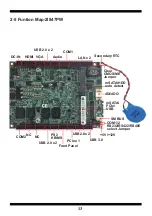
Страница 18: ...14 2 6 Diagram 2I847PW CPH2 CPH1 JSC1 JSC2 CPO1 CO1 CIO1 CBAT1 JSB12 MPCE1 MPCE2 TOP...

Страница 19: ...15 2 6 1 Diagram 2I847PW BOT SATA1...

Страница 20: ...OFF as an open circuit without the plastic cap Some jumpers have three pins labeled 1 2 and 3 You could connect either pin 1 and 2 or 2 and 3 The below figure 2 2 shows the examples of different jump...

Страница 21: ...clear the CMOS follow the procedures below 1 Turn off the system and unplug teh AC power 2 Remove DC 12V power cable from DC 12V power connector 3 Locate JSB1 and close pin 1 2 for few seconds 4 Retu...

Страница 22: ...COM1 COM2 RS232 RS422 RS485 select JSC1 JSC2 RS232 RS422 RS485 1 2 Short Short Open 3 4 Open Short Open Note RS232 RS422 485 setting by both H W jumper and BIOS setting 4 2 JSC1 COM1 1 1 3 3 4 2 JSC2...

Страница 23: ...off the board before you install the peripherals CPH1 2 x 40 Pin 2 00mm Male CPH2 2 x 40 Pin 2 00mm Male CBAT1 Li 3V battery 2pin 1 25mm wafer CPO1 DC 5 12V output 1x6 pin 1 25mm Black wafer connector...

Страница 24: ...A17 B17 USB_P0_D USB_P1_D A18 B18 USB_P1_D GND A19 B19 GND GND A20 B20 USB_P01_VCC LINE_OUT_R A21 B21 LINE_IN_R MIC_IN_R A22 B22 MIC_IN_L LINE_OUT_L A23 B23 LINE_IN_L GND A24 B24 GND DSR1 A25 B25 DCD...

Страница 25: ...B19 USB_P23_VCC KB_CLK A20 B20 KB_DATA MS_CLK A21 B21 MS_DATA GND A22 B22 GND POWER SWITCH A23 B23 RESET SWITCH SMB_DATA A24 B24 POWER_LED_N SMB_CLK A25 B25 HDD_LED_N V3 3S A26 B26 LAN_LED_N GND A27 B...

Страница 26: ...22 CHP1 pin1 CHP2 pin1...

Страница 27: ...r 3 4 DC voltage output PIN NO Description 1 5V 2 5V 3 GND 4 GND 5 12V 6 12V PIN NO Description 1 GND 2 VBAT Note 1 Battery use Li 3V 220mAh CR2032 2 When board without Adaptor plug in this board powe...

Страница 28: ...rnal device 3 F75111N 1 I2 C bus address 0x9c For F75111N I2 C watch dog timer device DC spec Input low Voltage VIL 0 8 Max Input High Voltage VIH 2V Min Output low Current IOL 10mA Min VOL 0 4V Outpu...

Страница 29: ...AME PASSWORD sf 1 Boot Ms Dos Operating System 2 execute 75WDT EXE binary file 3 Input 1 to Enable WDT timer or input 0 to Disable it 4 input numbers of second for chip countdown and Reset Computer ht...

Страница 30: ...DDR WDT_TIMER timer Set Watch Dog Timer range from 0 255 WriteI2CByte I2CADDR WDT_TIMER_CTL 0x73 Enable Watch Dog Timer in second and pulse mode void pause int time asm mov ah 0h Ah 00 Read System Tim...

Страница 31: ...demo test with a test tool which DIx connect to DOx with Relay Source file F75111_DIO_Src_v2 8W 32bit zip Binary file F75111_DIO_Bin_v2 8W 32bit zip USERNAME PASSWORD sf http tprd info lexwiki index...

Страница 32: ...tem administrator to open DIO utility two F75111 1 Press the Start button to test DIO function 2 Press the Enable button to test WDT function 3 Press the Disable button to disable WDT 4 Check the Enab...

Страница 33: ...reboot if there s disable signal received resent Enable WDT signal for a loop to prevent from reboot F75111 Layout Picture Initial Internal F75111 port address 0x9c Set F75111 DI DO sample code as be...

Страница 34: ...R GPIO3X_CONTROL_MODE 0x00 set GPIO3X to Input function this Write_Byte F75111_INTERNAL_ADDR GPIO2X_CONTROL_MODE 0xFF set GPIO2X to Output function this Write_Byte F75111_INTERNAL_ADDR F75111_CONFIGUR...

Страница 35: ...Data byteData byteGPIO1X 0x20 byteData 0x80 byteData Get correct DI value from GPIO1X GPIO3X return byteData void F75111_SetWDTEnable BYTE byteTimer WriteByte F75111_INTERNAL_ADDR WDT_TIMER_RANGE byte...

Страница 36: ...X_PULSE_CONTROL 0x43 GPIO3x Level Pulse Control Register 0 Level Mode 1 Pulse Mode define GPIO3X_Output_Data 0x41 GPIO3x Output Data Register define GPIO3X_PULSE_WIDTH_CONTROL 0x44 GPIO3x Pulse Width...

Страница 37: ...der Windows A Function Choose your motherboard model B Function Enable WDT timer Key in the value by seconds then system will reboot after value which you key in in left text box C Function Disable WD...

Страница 38: ...bleWDT Function DisableWDT SDK Function Introduction Function EnableWDT timer As Integer Call WriteI2CByte H3 H3 Call WriteI2CByte H37 timer Call WriteI2CByte H36 H73 End Function Function DisableWDT...

Страница 39: ...ata H2 End If If Value And H4 0 Then Data Data H4 End If If Value And H80 0 Then Data Data H8 End If If Value And H40 0 Then Data Data H10 End If If Value And H20 0 Then Data Data H20 End If If Value...

Страница 40: ...0 GPIO3X GPIO3X And HF If GPIO1X And H10 0 Then Data Data H1 End If If GPIO1X And H80 0 Then Data Data H2 End If If GPIO1X And H40 0 Then Data Data H4 End If If GPIO3X And H1 0 Then Data Data H8 End I...

Страница 41: ...wnload and install the Code Block with command apt get install codeblocks Open an exist project F75111 cbp in Code Blocks click the compile button add an option pkg config libs gtk 2 0 gthread 2 0 in...

Страница 42: ...orun this application when booting press Uninstall to remove this application when booting 6 If WDT enable system icon will be blinking p s f75111 send F75111_SetWDTEnable BYTE byteTimer including a p...

Страница 43: ...O2X_CONTROL_MODE 0xFF set GPIO2X to Output function this Write_Byte F75111_INTERNAL_ADDR F75111_CONFIGURATION 0x03 Enable WDT OUT function Set output value void F75111 InterDigitalOutput BYTE byteValu...

Страница 44: ...teData byteData byteGPIO3X 0x01 byteData 0x08 byteData byteData byteGPIO3X 0x02 byteData 0x10 byteData byteData byteGPIO3X 0x04 byteData 0x20 byteData byteData byteGPIO3X 0x08 byteData 0x40 byteData b...

Страница 45: ...Configure WDT Function define WDT_TIMEOUT_FLAG 0x40 When watchdog timeout this bit will be set to 1 define WDT_ENABLE 0x20 Enable watchdog timer define WDT_PULSE 0x10 Configure WDT output mode 0 Level...

Страница 46: ...compatible 3 6 I2 C BUS CO1 I2 C Bus 4pin 1 25mm Wafer PIN NO Description 1 3 3V 2 GND 3 I2 C Clock 4 I2 C DATA CO1 pin1 pin1 SATA1 SATA connector 7pin wafer 3 7 SATA port PIN NO Description 1 GND 2...

Страница 47: ...KEY 17 NC 18 GND 19 NC 20 NC 21 GND 22 PRST 23 PCIe RX mSATA RX 24 3 3V 25 PCIe RX mSATA RX 26 GND 27 GND 28 1 5V 29 GND 30 SMB CLK 31 PCIe TX mSATA TX 32 SMB DATA 33 PCIe TX mSATA TX 34 GND 35 GND 3...

Страница 48: ...eted BIOS will give control of the computer back to operating system OS Since the BIOS is the only channel for hardware and software to communicate with it is the key factor of system stability and of...

Страница 49: ...l Help F2 Previous Values F3 Optimized Defaults F4 Save Exit Esc Exit Menu Items Function Keys General Help Items Current Setting Value Menu Bar 4 3 Function Keys In the above BIOS Setup main menu of...

Страница 50: ...selections for the highlighted item To exit the Help Window press Esc 4 5 Menu Bars There are six menu bars on top of BIOS screen Main To change system basic configuration Advanced To change system a...

Страница 51: ...Time 19 28 51 Select Screen Select Item Enter Select Change Opt F1 General Help F2 Previous Values F3 Optimized Defaults F4 Save Exit Esc Exit Version 2 14 1219 Copyright C 2011 American Megatrends In...

Страница 52: ...Optimized Defaults F4 Save Exit Esc Exit Version 2 14 1219 Copyright C 2011 American Megatrends Inc ACPI Settings Please refer section 1 7 1 S5 RTC Wake Settings Please refer section 1 7 2 CPU Config...

Страница 53: ...ized Defaults F4 Save Exit Esc Exit Version 2 14 1219 Copyright C 2011 American Megatrends Inc Enable ACPI Auto Configuration This item allows you to Enabled Disabled the Advanced Configuration and Po...

Страница 54: ...F2 Previous Values F3 Optimized Defaults F4 Save Exit Esc Exit Version 2 14 1219 Copyright C 2011 American Megatrends Inc Wake system with Fixed Time Use this item to Enable or Disable system wake on...

Страница 55: ...Intel Virtualization Technology Disabled Select Screen Select Item Enter Select Change Opt F1 General Help F2 Previous Values F3 Optimized Defaults F4 Save Exit Esc Exit Version 2 14 1219 Copyright C...

Страница 56: ...lect Screen Select Item Enter Select Change Opt F1 General Help F2 Previous Values F3 Optimized Defaults F4 Save Exit Esc Exit Version 2 14 1219 Copyright C 2011 American Megatrends Inc SATA Controlle...

Страница 57: ...de Selection IDE SATA Controller Speed Gen3 Select Screen Select Item Enter Select Change Opt F1 General Help F2 Previous Values F3 Optimized Defaults F4 Save Exit Esc Exit Version 2 14 1219 Copyright...

Страница 58: ...Exit Version 2 14 1219 Copyright C 2011 American Megatrends Inc Legacy USB Support Enables Legacy USB support AUTO option disables legacy support if no USB devices are connected Disable option will k...

Страница 59: ...iguration F71869 Super IO Chip F71869 Serial Port 1 Configuration Serial Port 2 Configuration Power Failure Keep last state Select Screen Select Item Enter Select Change Opt F1 General Help F2 Previou...

Страница 60: ...ults F4 Save Exit Esc Exit Serial Port Use this item to enable or disable serial port COM The optional settings are Enabled Disabled Device Settings Serial Port 1 IO 3F8h IRQ 4 Change Settings Use thi...

Страница 61: ...ngs are Enabled Disabled Device Settings Serial Port 2 IO 2F8h IRQ 3 Change Settings Use this item to select an optimal setting for super IO device The optional settings are AUTO IO 2F8h IRQ 3 IO 3F8h...

Страница 62: ...4 Save Exit Esc Exit Console Redirection Use this item to enable or disable Console Redirection The optional settings are Enabled Disabled 4 7 10 Network Stack Main Advanced Chipset Boot Security Save...

Страница 63: ...SA Configuration Select Screen Select Item Enter Select Change Opt F1 General Help F2 Previous Values F3 Optimized Defaults F4 Save Exit Esc Exit Version 2 14 1219 Copyright C 2011 American Megatrends...

Страница 64: ...AN Disabled Select Screen Select Item Enter Select Change Opt F1 General Help F2 Previous Values F3 Optimized Defaults F4 Save Exit Esc Exit Version 2 14 1219 Copyright C 2011 American Megatrends Inc...

Страница 65: ...press Configuration Mini PCIe 1 Mini PCIe 2 PCI Express Root Port 5 Select Screen Select Item Enter Select Change Opt F1 General Help F2 Previous Values F3 Optimized Defaults F4 Save Exit Esc Exit Ver...

Страница 66: ...Gen1 Select Screen Select Item Enter Select Change Opt F1 General Help F2 Previous Values F3 Optimized Defaults F4 Save Exit Esc Exit Version 2 14 1219 Copyright C 2011 American Megatrends Inc PCI Exp...

Страница 67: ...1 General Help F2 Previous Values F3 Optimized Defaults F4 Save Exit Esc Exit Version 2 14 1219 Copyright C 2011 American Megatrends Inc XHCI Pre Boot Driver Use this item to enable or disable XHCI Pr...

Страница 68: ...lect Screen Select Item Enter Select Change Opt F1 General Help F2 Previous Values F3 Optimized Defaults F4 Save Exit Esc Exit Version 2 14 1219 Copyright C 2011 American Megatrends Inc HS Port 1 Swit...

Страница 69: ...Exit Esc Exit Version 2 14 1219 Copyright C 2011 American Megatrends Inc Azalia Use this item to enable disable or auto control detection of the Azalia device Azalia Dcoking Support Use this item to e...

Страница 70: ...zed Defaults F4 Save Exit Esc Exit Version 2 14 1219 Copyright C 2011 American Megatrends Inc Aperture Size The optional settings are 128MB 256MB 512MB DVMT Pre Allocated Use this item to select DVMT...

Страница 71: ...Display HDMI Select Screen Select Item Enter Select Change Opt F1 General Help F2 Previous Values F3 Optimized Defaults F4 Save Exit Esc Exit Version 2 14 1219 Copyright C 2011 American Megatrends Inc...

Страница 72: ...Item Enter Select Change Opt F1 General Help F2 Previous Values F3 Optimized Defaults F4 Save Exit Esc Exit Version 2 14 1219 Copyright C 2011 American Megatrends Inc Bootup NumLock State Use this ite...

Страница 73: ...ange Opt F1 General Help F2 Previous Values F3 Optimized Defaults F4 Save Exit Esc Exit Version 2 14 1219 Copyright C 2011 American Megatrends Inc Boot option filter This option controls what devices...

Страница 74: ...he password length must be in the following range Minimum length 3 Maximum length 20 Administrator Password User Password Select Screen Select Item Enter Select Change Opt F1 General Help F2 Previous...

Страница 75: ...ect Screen Select Item Enter Select Change Opt F1 General Help F2 Previous Values F3 Optimized Defaults F4 Save Exit Esc Exit Version 2 14 1219 Copyright C 2011 American Megatrends Inc Save Changes an...

Страница 76: ...s auto detect software SYSTEM INSTALL 1 Auto Detect Main board and OS to AUTOMATIC DRIVER INSTALLATION menu 2 Browse DVD to view the contents of the DVD 3 Exit to exit SYSTEM INSTALL menu DRIVER INSTA...

Страница 77: ...oard VGA driver 3 SOUND install VIA HD Audio Codec driver 4 LAN to the LAN driver Readme file 5 COM to the COM driver Readme file 6 USB 3 0 install Intel USB 3 0 extensible Host Controller driver Each...

Страница 78: ...dge Chipset Driver 1 At the AUTOMATIC DRIVER INSTALLATION menu screen click INF 3 At the License Agreement screen click Yes 2 At the Intel Chipset Device Software screen click Next 4 At the Readme Fil...

Страница 79: ...computer NOTE SYSTEM INSTALL will auto detect file path For Windows XP 64 32 bit Windows 7 64 32 bit and windows 8 64 32 bit X driver INTEL IVY_SAN inf infinst_autol exe For Windows 8 1 64 32 bit X d...

Страница 80: ...ridge VGA Driver 1 At the AUTOMATIC DRIVER INSTALLATION menu screen click VGA 3 At the Welcome to the Setup Program screen Click Next 2 At the Intel HD Graphics Driver screen Click Next 4 At the Licen...

Страница 81: ...64 winxp64_145110 exe For Windows XP 32bit X driver INTEL IVY_SAN vga winxp winxp_145110 exe For Windows 7 64bit and Windows 8 64bit X driver INTEL IVY_SAN vga WIN_7_8_64 win64_152812 exe For Windows...

Страница 82: ...INSTALL will auto detect file path For Windows XP 32 64 bit X driver INTEL IVY_SAN SOUND WDM_R270 exe For Windows 7 32 64 bit and Windows 8 32 64 bit X driver INTEL IVY_SAN SOUND Vista_Win7_Win8_R270...

Страница 83: ...Controller Driver 1 At the AUTOMATIC DRIVER INSTALLATION menu screen Click USB 3 0 3 At the License Agreement screen Click Yes 2 At the Intel USB 3 0 extensible Host Controller Driver screen Click Nex...

Страница 84: ...80 5 Click Next 6 Click Finish to restart computer NOTE The path of the file For Windows 7 32 64 bit X driver INTEL IVY_SAN USB3_0 INTEL Setup exe...

Страница 85: ...l Management Engine Interface Driver 1 Plaese Check Device Manager PCI Simple Communications Controllers 3 At the Setup Progress screen Click Next 2 At the Intel Management Engine Components screen Cl...

Страница 86: ...ck Finish 6 Plaese Check Device Manager PCI Simple Communications Controllers NOTE The path of the file For Windows XP 32 64 bit and Windows 7 32 64 bit X driver INTEL ME TOOL MEI Only Installer MEISe...

Страница 87: ...83 5 6 How to update AMI BIOS Step 1 To run afuwingui exe then click Open Step 2 Click the new version BIOS download from the website...

Страница 88: ...84 Step 3 Choose ProgramAll Blocks and Do Not Check ROM ID Step 4 Click Flash Step 5 Click Exit and restart computer...

Страница 89: ...ase enter your motherboard s name Insert your bootable disc into X X could be C A or others It depends on which type of storage device you use Start the computer and type X H2OFFT D EXE 2I847PWA2 ROM...

Страница 90: ...4 Ghz SDRAM DDR3 1333 4GB Operating System Windows 7 SP1 Test Program 3D Mark 06 HDD 2 5 SATA Slim Type HDD mSATA 32GB Hard Disk Power off Start up Operation Maximum Shut down Maximum In Put Voltage...

Страница 91: ...bit 32bit 1280 x 720 x 256 16bit 32bit 1280 x 768 x 256 16bit 32bit 1280 x 800 x 256 16bit 32bit 1280 x 960 x 256 16bit 32bit 1280 x 1024 x 256 16bit 32bit 1400 x 1050 x 256 16bit 32bit 1440 x 900 x 2...

Отзывы: