


8
Chapter-2
This chapter provides the information how to install the hardware of 2I847PW.
2-1 and 2-2 to check the delivery package and unpack carefully. Please follow the jumper
setting procedure.
You should follow these
steps to protect the board from the static electric
discharge whenever you handle the board:
1. Ground yourself by a grounded wrist strap at all times when you handle the 2I847PW.
Well secure the ALLIGATOR clip of the strap to the end of the shielded wire lead from
a grounded object. Please put on and connect the strap before handling the
2I847PW for harmlessly discharge any static electricity through the strap.
2. Please use anti-static pad to put any components, parts, or tools on the pad whenever
you work on them outside the computer. You may also use the anti-static bag instead of
the pad. Please ask your local supplier for necessary parts on anti-static requirement.
3. Do not plug any connector or set any jumper when the power is on.
Hardware Installation
2-1 Unpacking Precaution
NOTE!
1. Do not touch the board or any other sensitive components without all necessary
anti-static protection.
2. Please pay attention to the voltage limitation of DC-IN12V 5%.
Overuse of DC-IN voltage limitation or change to another power adapter
(not provided with this system) will VOID warranty.
Содержание 2I847PW
Страница 7: ...3 2 1 3 1 2 3 Photo 1 Insert Unplug...
Страница 14: ...10 2 3 Dimension 2I847PW...
Страница 15: ...11 2 4 Layout 2I847PW CPH2 CPH1 JSC1 JSC2 CPO1 CO1 CIO1 CBAT1 JSB12 MPCE1 MPCE2 TOP...
Страница 16: ...12 2 4 1 Layout 2I847PW SATA1 BOT...
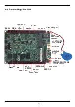
Страница 18: ...14 2 6 Diagram 2I847PW CPH2 CPH1 JSC1 JSC2 CPO1 CO1 CIO1 CBAT1 JSB12 MPCE1 MPCE2 TOP...
Страница 19: ...15 2 6 1 Diagram 2I847PW BOT SATA1...
Страница 26: ...22 CHP1 pin1 CHP2 pin1...


