background image


User Manual for BPS-200 

www.levitronix.com 


PL-4012-00, Rev07, DCO# 20-144 


34


Appendix 

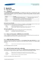
9.1  Regulatory Status 

9.1.1  CE Marking 

The 

Centrifugal  Pump  System  Family  BPS-200

,  in  its  configurations  as  listed  below  is  in  conformity  with  the  below 

mentioned 

European  Directives

.  The  various  configurations  of  the  pump  system  are  thought  to  be  used  in  hydraulic 

circuits of industrial production equipment of the Semiconductor, Chemical, Life Science (Biotech, Pharmaceuticals) and 
other machinery markets. 
 

Part Name 

Description 

LPP-200.x 

Pump casing configurations consisting of variations 
concerning fittings, O-Rings, wet materials and performance 

and impellers with various materials and 
performance variations 

BSM-1.x  

Bearingless motors: 

BSM-1.x

 (x = various cable, connector and coating options) 

LPC-200.x 

Controllers with 24 

– 48V DC inputs: 

LPC-200.x

 (x = various interfacing options) 

Accessories 

Motor controller adaptor cables of various length, air cooling module and others 


Machinery Directive 2006/42/EC:  

The machinery directive essentially has been followed by a risk analysis, according mitigation actions and a user manual 
for safe operation. For the design and testing the following standards are used as a guideline: 

EN809 

Pumps for Fluids: basic requirements are followed. 

EN12162 

Procedure for hydrostatic pressure testing in fluid pumps: used for max. pressure testing of pump head. 

ISO12100 

Safety for machinery 

– principles for risk assessments: used for system risk analysis. 


EMC Directive 2014/30/EC: 

The following standards of the EMC directive are tested and confirmed at a certified laboratory: 

EN61000-6-2 

Generic standards, Immunity for industrial environments 

EN61000-6-4 

Generic standards, Emission standard for industrial environments 


9.1.2  Disposal of Equipment 

– WEEE Directive 2012/19/EU 

Follow local legislation for disposal of equipment. In the European Union (EU) marked (

) devices are governed by the 

European WEEE Directive 2012/19/EU. Do not dispose with normal waste.


9.1.3  IECEE CB Safety Certification 

Specific  motors  with  pump  heads  and  controllers  of the 

Centrifugal  Pump  System  BPS-200 

are  3

rd

  party 

tested  and  certified  by 

Electrosuisse

  following  the 

IECEE  CB  Scheme

  according  to  the  following  safety 

standards: 


IEC61010-1 

Safety requirements for electrical equipment for measurement, control and laboratory use. 


The CB certification number is 

CH-7695

.  


9.1.4  NRTL/ETL Safety Certification and Marking 

Specific motors with pump heads and controllers of the 

Centrifugal Pump System BPS-200 

are tested by 

the US national recognized laboratory (NRTL) 

Intertek

 according to the following safety standards: 


UL61010-1 

Safety requirements for electrical equipment for measurement, control and laboratory (US Standard).


CSA-C22.2  
No. 61010-1-12 

Safety requirements for electrical equipment for measurement, control and laboratory use (Canadian Standard).


UL1004-1 

Rotating Electrical Machines - General Requirements (US standard). 

 
The ETL control number for the listing is 

4010272


Содержание BPS-200

Страница 1: ...use installation operation adjustment inspection and maintenance For special configurations of the pump system refer to accompanying information If the system must be configured for other parameter settings then the Levitronix Service Software version V2 0 5 0 or higher with according manual Levitronix Doc PL 4046 00 is necessary Familiarize yourself with the contents of the manual to ensure the s...

Страница 2: ...3 Mechanical Installation of Motors in Ex Classified Areas 23 4 4 Mechanical Installation of the Controller 23 4 5 Mechanical Installation of Adaptor Extension Cables 24 5 OPERATION 25 5 1 System Operation with LPC 200 1 Stand Alone Version 25 5 1 1 State Diagram of LPC 200 1 25 5 1 2 Standalone Operation Button Control Mode 26 5 1 3 Extended Operation Analog Control Mode 26 5 1 4 Errors Display o...

Страница 3: ...WARNING Hazardous voltage may be present In case of the usage of an inadequate AC DC power supply mains voltages may be present even if the system is designed for 24 48VDC The usage of a galvanic separated power supply which is certified by a 3rd party UL or CE is highly recommended The controller must be grounded and placed in a spill protected electrical cabinet Do not under any circumstances op...

Страница 4: ...omponents Figure 1 shows the main system components motor controller and pump head together with the system accessories and Figure 2 illustrates the accessories for the pump system Figure 1 Pump system BPS 200 with standard components Figure 2 Accessories 1 2a 3a 3b 2c 2b 8f 8c 8b 8e 9 5 6 4 7a 7b 7c 7e 7d 8a 8d ...

Страница 5: ...C Dc 3a Standalone Controller User Panel LPC 200 1 100 30008 Controller with PLC connector incl in 100 90335 Electrical Power Voltage 200 W 24 48V DC Interfaces for Standalone Controller Panel to set speed automatic storage on internal EEPROM PLC with 1x analog input Speed 4 20 mA 1x digital input Enable 0 24 V optocoupler 1x digital output Status 0 24 V relais Standard Firmware C2 25 3b Extended ...

Страница 6: ... A USB interface allows communication with a PC in connection with the Levitronix Service Software Hence parameterization firmware updates and failure analysis are possible Figure 4 Standard system configuration for extended operation Pressure or flow control with external sensor Chemical Resistance and IP67 Space Motor Pump Head Fluid In Fluid Out Motor Cable Adaptor Extension Power Supply 24 48 ...

Страница 7: ...ea Ex Classified Location Chemical Resistance and IP 67 Space Motor ATEX IECEx Figure 5 System configuration for ATEX IECEx applications 2 3 General Environmental Conditions Usage Indoor 1 Altitude Up to 2000 m Operating ambient temperature 0 to 40 0C Storage ambient temperature Extremes for Transportation 20 to 80 0C Operating humidity range relative humidity 15 95 non condensing Storage humidity...

Страница 8: ... in longer term deformation effects of the standard PVDF screws 0 10 20 30 40 0 0 1 0 2 0 3 0 4 0 5 0 6 0 0 0 0 5 1 0 1 5 2 0 2 5 3 0 0 0 2 5 5 0 7 5 10 0 12 5 15 0 17 5 20 0 22 5 25 0 psi gallons min bar liters min Specific gravity 1 g cm3 Viscosity 0 7 cP Liquid Temp 40C 8000 rpm 7000 rpm 6000 rpm 5000 rpm Supply Voltage 24 V DC Speed Limit for 24V 9500 rpm Speed Limit for 48V 10000 rpm 9000 rpm...

Страница 9: ...com PL 4012 00 Rev07 DCO 20 144 9 2 6 Basic Dimensions of Main Components Figure 8 Basic dimensions in mm and inch of motor BSM 1 x with pump head LPP 200 1 Same dimensions with LPP 200 11 For other configurations refer to according drawings ...

Страница 10: ...FEP 8 50 mm 7x Cable OD 15 x Cable OD PVC 9 50 mm 5x Cable OD 11 x Cable OD Table 6 Specifications for min bending radius of motor and adaptor cables for BSM 1 Note If not mentioned explicitly all the cables are not suited for constant dynamic bending and movement Figure 9 Basic dimensions in mm of controller LPC 200 2 Same basic dimensions for LPC 200 1 Alternative for mounting DIN rail clips ...

Страница 11: ...ws for pump casing PVDF Option Stainless Steel PTFE Coating to be ordered separately see Table 4 4 Impeller LPI 200 1 PFA 5 Rotor magnet Rare earth material 6 4 M3x14mm screws for pump motor mounting PEEK Motor BSM 1 3 7 Sealing O ring for motor housing FPM FKM 8 Cable bushing FPM cable jacket is FEP 9 Motor housing ETFE coating waterproof IP 67 Coils and electromagnetic circuit potted with an epo...

Страница 12: ...motor temperature 90 C 194 F for a duration of more than 10 minutes the system goes into an error state and the pump stops At 80 C 176 F controller temperature or 100 C 212 F motor temperature the system stops immediately Start Temperature Monitoring WARNING YES Temperature 70 C Temperature 80 C YES YES ERROR Temperature higher than 70 C for more than 10 minutes NO ERROR YES NO NO Start Temperatur...

Страница 13: ...gure 15 Temperature curves for the BSM 1 x motor 70 C liquid temperature Pumping with pump head LPP 200 1 temperature is measured inside of the motor contact temperature is below this temperature Curves are representative for LPP 200 11 77 97 117 137 157 177 197 0 0 1 0 2 0 3 0 4 0 5 0 6 0 25 35 45 55 65 75 85 95 0 0 2 5 5 0 7 5 10 0 12 5 15 0 17 5 20 0 22 5 25 0 F gallons min 0C liters min Ambien...

Страница 14: ...e curves 77 97 117 137 157 177 197 0 0 1 0 2 0 3 0 4 0 5 0 6 0 25 35 45 55 65 75 85 95 0 0 2 5 5 0 7 5 10 0 12 5 15 0 17 5 20 0 22 5 25 0 F gallons min 0C liters min Ambient Temp 25 C Liquid Temp 90 C Specific gravity 1 g cm3 Viscosity 0 7 cP Air cooling with ACM 1 1 0 5 bar 20 C air 9000 rpm Absolute Temp Limit Recommended Operational Limit 8000 rpm 7000 rpm 6000 rpm 10000 rpm Supply 24 VDC Suppl...

Страница 15: ...g the thermal concept of the pump system 3 4 2 Controller Temperature Depending on the ambient temperature and the placement of the controller additional cooling may be required see Figure 18 To improve cooling of the controller place the device into a moving air stream If the controller is mounted in a compact area or adjacent to additional heat sources e g a 2nd controller ensure that there is s...

Страница 16: ...circuit shall be designed in a way that gas bubbles can leave the pump housing and that the pump head remains primed 7 To minimize heat up of the liquid the overall pressure drop in the hydraulic circuit shall be reduced as much as possible 8 It shall be avoided to pump longer times against a closed valve which can cause heat up of the liquid 9 At flows 1 l min it is recommended to use a bypass lo...

Страница 17: ...t Galvanic isolation with optocoupler Lowest input voltage for high level detection min 5 V Typical 24 V 16 mA maximal 30 V 20 mA Highest input voltage for low level detection max 0 8 V Minimum input resistance RIN 2 2 k 1 Digital Output Galvanic isolation with relay Relay 1A 30VDC 0 3A 125 VAC 1 Analog Input Analog current input 4 20 mA 450 Ohm shunt input 3 POWER INPUT DC power input 24 48 V 4 P...

Страница 18: ...ection no galvanic isolation Max output current 2mA 4 Digital Input Galvanic isolation with optocoupler Lowest input voltage for high level detection min 5 V Typical 24 V 16 mA maximal 30 V 20 mA Highest input voltage for low level detection max 0 8 V Minimum input resistance RIN 2 2 k 4 Digital Output Galvanic isolation with relay Relay 1A 30VDC 0 3A 125 VAC 3 USB USB interface 4 POWER INPUT DC p...

Страница 19: ...ail brackets can be used for grounding see Figure 22 2 Connect the motor connector to the controller 3 Connect the controller type specific connectors see Section 4 1 3 for standalone operation with the LPC 200 1 Section 4 1 4 for extended operation with LPC 200 1 and Section 4 1 5 for extended operation with LPC 200 2 4 Depending on the required hydraulic operational point see Figure 6 the pump s...

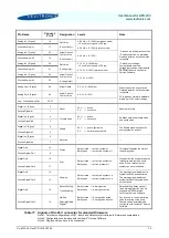
Страница 20: ...in Table 10 Pin Name Connector Pin Number Designation Levels Note Analog In Signal 5 Reference Speed 4 20 mA 0 10000 rpm Cut off min speed 300 rpm Direct connection no protection Galvanic isolation on the user side is required Ground Analog In 6 Digital In Signal 3 Enable 24 V active 0 V not active Is needed to enable the system with an external signal Ground Digital In 4 Digital Out 1 Status Rela...

Страница 21: ...d from the controller electronics To avoid ground loops and mal functions use floating analog signals 1 Detach the PLC connector from the controller 2 Connect the designated wires of a cable the pins of the detached connector according to Table 11 Assignment and functions of the I Os can be changed with the controller firmware version refer to according firmware documentation 3 Connect the PLC con...

Страница 22: ...6 Enable 24 V active system on 0 V not active system off The Enable signal switches the pump system on and off Ground Digital In3 5 Digital In4 Signal 8 Not used Ground Digital In4 7 Digital Out1 10 Status Relay closed active system on Relay open not active system off This signal indicates the state of the pump system Ground Digital Out1 9 Digital Out2 12 Error Relay closed not active system on Re...

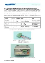
Страница 23: ...se a crimp type end together with a spacer sleeve to connect a earth wire Attach the grounding wire with a M4 stainless steel screw to the motor according to Figure 27 Figure 27 Attachment of a protective earth wire to the backside of the motor 4 4 Mechanical Installation of the Controller WARNING Hazardous voltage may be present In order to avoiding fluid spills shorting mains or other voltages w...

Страница 24: ...or cables MCA 1 x shall be used ed see Table 3 for adaptor cables For the cables which use an M23 threaded metallic Hummel connector type check the connection according to the following pictures Figure 28 Wrong and correct Hummel connector type assembly O Ring visible Wrong Connection O Ring not visible Correct Connection Gap 2 mm Sensor Cable of Motor Gap 2 mm Sensor Adaptor Cable ...

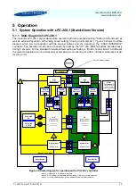
Страница 25: ...ol Mode Analog Control Mode Power On OFF ButtonControl ON Speed Mode ButtonControl Ref Speed set to stored value OFF AnalogControl ON Speed Mode AnalogControl Ref Speed set by analog input R Reset Button Ref Speed UP Ref Speed DOWN ButtonControl saved in EEPROM AnalogControl saved in EEPROM Error Error Enable input 0V Enable input 0V Enable input 24V Press up for 2 sec Press down for 2 sec Press u...

Страница 26: ...cally when power is applied the ENABLE pin on the USER INTERFACE connector see Table 10 has to be active typically 24V When switching on the power the system is running with the stored speed For monitoring purposes a digital output on the USER INTERFACE connector see Table 10 indicates the status of the system When the impeller is rotating the digital output Status turns active The digital input E...

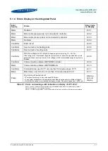
Страница 27: ...of extended range the system is disabled Er 08 Controller Communication problems EEPROM Controller Er 09 Motor Communication problems EEPROM Motor Er 10 Controller Controller temp over 80 0C or more than 10 minutes above 70 0C Er 11 Motor Motor temp over 100 0C or more than 10 minutes above 90 0C Er 12 Pump Dry running of pump circuit Pump keeps running on reduced speed 5000 rpm The system acceler...

Страница 28: ...e State 1 Power On ON Speed Control Mode Status Active Error not active State 5 ERROR Status not active Error active State 4 Priming off Enable active Reset not active Reset active ON Process Control Mode Status Active Error not active State 6 Internal Error Internal Error Enable not active Process Mode active Process Mode not active ON Priming Mode Status active Error not active State 10 Priming ...

Страница 29: ...r than 90 C for more than 10 minutes Error relay open Motor Temperature more than 90 C Warning relay open Motor No motor temperature signal Warning relay open Motor Motor power cable not connected with controller Error relay open Motor Motor sensor cable not connected with controller Error relay open Controller Over current in the bearing coils Error relay open Controller Power channel interrupted...

Страница 30: ...he LPC 200 2 controller the Digital Out 3 of the PLC connector see Table 11 shall be monitored for warnings during operation in order to check if the communication to the temperature sensor is established If Digital Out 3 is active this output indicates warnings caused by various sources inter alia communication problems with the motor the pump system may be checked for correct operation The motor...

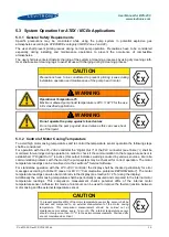
Страница 31: ...O rings and screws Figure 31 Explosion view of pump head with motor Figure 32 Components for impeller replacement The following warnings and cautions should be read carefully before starting the replacement of the impeller WARNING The impeller could splash TOXIC or CORROSIVE CHEMICALS because of the strong magnetic forces Flush the pump housing before opening it WARNING HARMFUL CHEMICALS may be pr...

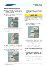
Страница 32: ... If necessary consult the Levitronix Technical Service Depart ment Do NOT twist or roll the O Ring and avoid to adding scratches or particles as this may cause leaking 7 Press the lid with the O ring flush into the bottom of the pump casing 8 Carefully tighten the 6 pump casing screws The screws should not be used to press the lid with the O ring into the bottom of the pump casing Do not apply too...

Страница 33: ...s a Warning and an Error signals according to Table 13 However the source of error cannot be identified by these signals For more detailed analysis the Levitronix Service Software can be used with a PC and a USB interface to the controller 7 3 Troubleshooting with Levitronix Service Software The Levitronix Service Software allows communication with the pump system in connection with a PC and a USB...

Страница 34: ... Safety for machinery principles for risk assessments used for system risk analysis EMC Directive 2014 30 EC The following standards of the EMC directive are tested and confirmed at a certified laboratory EN61000 6 2 Generic standards Immunity for industrial environments EN61000 6 4 Generic standards Emission standard for industrial environments 9 1 2 Disposal of Equipment WEEE Directive 2012 19 E...

Страница 35: ...s IEC EN 60079 31 Explosive atmospheres Part 31 Equipment dust ignition protection by enclosure t IEC EN 13463 1 Non electrical equipment for use in potentially explosive atmospheres Part1 Basic method and requirements IEC EN 13463 5 Non electrical equipment for use in potential explosive atmospheres Part5 Protection by constructional safety c The Levitronix Ex motors are marked clearly and in acc...

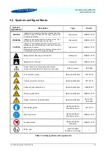
Страница 36: ...ot avoided could result in property damage Signal word SEMI S1 0701 Safety alert for Warning and Caution Safety alert SEMI S1 0701 Safety alert for Danger Safety alert SEMI S1 0701 Caution refer to accompanying documents is used on article labels for reference to manual Refer to manual ISO 3864 Toxic material poison Hazard identification IEC 61310 Corrosive material corrosion Hazard identification...

Отзывы: