User Manual for BPS-i600
www.levitronix.com
PL-4089-00, Rev00, DCO# 21-271
6
2.2 System Overview and General Specification
2.2.1 Standard System Configuration for Speed Control
When using the pump system in speed control mode, the speed can precisely be set via an analog input.
Various digital inputs and outputs allow controlling and monitoring of the system. A
RS485
enables
communication with a PC with the
Levitronix
®
Service Software
. Hence parameterization, firmware updates
and diagnostics are possible. The
RS485
can also be used as a fieldbus to implement more intelligent concepts
of pump control.
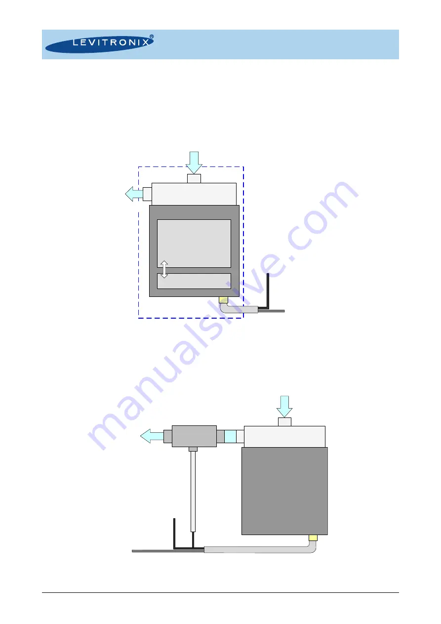
Figure 3: Standard system configuration for speed control
(details in Section 4.1.1
2.2.2 Standard Configuration for Process Control
The
PLC
interface of the pump system enables the implementation of precise closed loop flow or pressure
control in connection with either a flow or pressure sensor (see
). Precise ultrapure flow control
systems can be realized with the pump system in combination with
LEVIFLOW
®
flowmeters.
Figure 4: Standard system configuration for process control
(Pressure or flow control with external sensor, details in Section 4.1.1)
Chemical Resistance Area
Integrated Pump Driver
Integrated Pump Motor
Integrated Pump Controller
DC Power
Supply
Levitronix
Pump Head
Outlet
Inlet
- PLC:
-> Digital In1:
Enable
-> Digital In2:
Process Mode
-> Digital Out1:
Status
-> Digital Out2:
Error
-> Analog In1:
Actual Process Value
-> Analog In2:
Ref Value
-> Analog Out:
Actual Speed
- Field Bus:
-> RS485: Extended Operation, Service
Integrated Pump Driver
DC Power Supply
Levitronix
Pump Head
Outlet
Inlet
- PLC:
-> Digital In1: "Enable"
-> Digital In2: "Process Mode" (Active)
-> Digital Out1: "Status"
-> Digital Out2: "Error"
-> Analog In2: "Ref. Process Value"
-> Analog Out: "Actual Process Value"
- Field Bus:
-> RS485 (Extended Operations)
Analog In1:
"Actual Process Value"
Flow or Pressure
Sensor


