


User Manual for BPS-4H (High Temp.)
www.levitronix.com
PL-2009-03, Rev04, DCO# 21-101
29
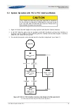
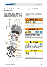
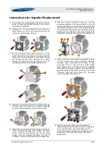
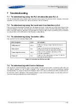
5.3 System Operation with PLC-A PLC Interface-Module
CAUTION
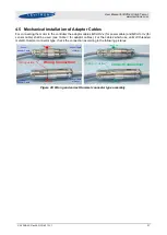
This chapter describes the analog and digital I/Os for the BPS-4
in the standard configuration. State diagram and signal names
can vary with other controller firmware versions. Please refer to
the separate firmware documentation.
▪
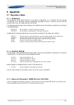
shows the state diagram for pump operation with the
PLC-Interface Module
.
▪
In the “Off” state the system can be operated via
RS-232
(handheld
Levitronix User Interface
or
Levitronix
®
Service Software
) without affecting the
PLC-Interface Module
state diagram. In all other
states
RS-232
commands are ignored.
▪
To set reference speed a current signal has to be feed to Analog Input 1 (see
Off
Status :
not active
State 1
Power On
ON
(Speed Control Mode)
Status :
Active
Error :
not active
State 5
ERROR
Status :
not active
Error :
active
State 4
Enable:
active
Reset:
not active
Reset:
active
ON
(Process Control
Mode)
Status :
Active
Error :
not active
State 6
Internal Error
Internal Error
Enable:
not active
Process Mode:
active
Process Mode:
not active
Figure 31: PLC-A.1 PLC-interface module, state diagram for firmware S4.48
(For other configurations see separate firmware documentation)