background image

9

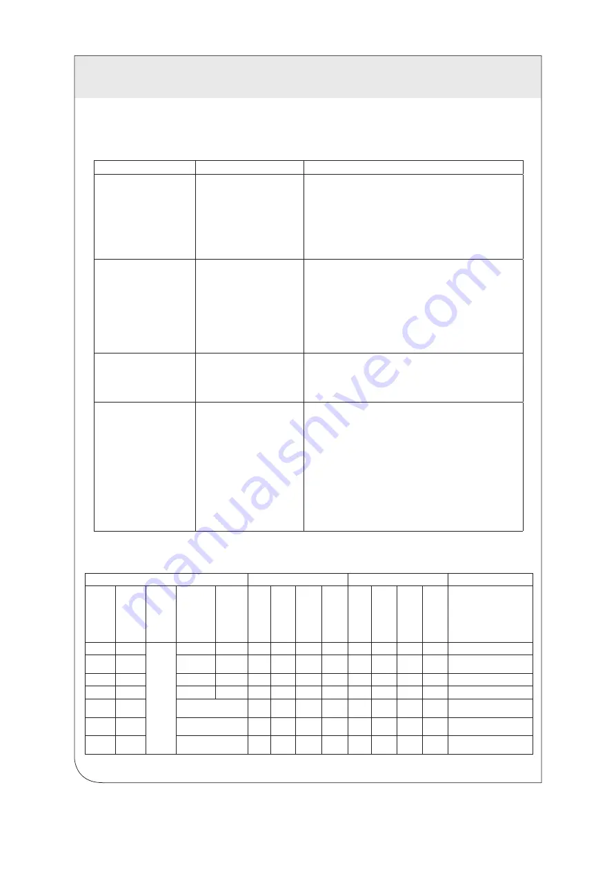
The following table provides troubleshooting tips. The topics are arranged in the order in which they should be executed in 
most situations. If you are unable to resolve the problem after following these instructions, please contact Technical Support 
for further assistance (1-800-824-3005).

TROUBLESHOOTING

Problem

Cause

Solution

USB device is attached but
not functioning

•   The USB device requires 

drivers that were not 
installed

•   The USB device does not 

support USB hubs

•   The USB device has 

malfunctioned

1.  Install the required USB device driver on the computer 

operating system prior to attaching the USB device into 
the Receiver. Please see your USB device manufacturer’s 
documentation for details.

2.  In the Universal Serial Bus controllers section of Device 

Manager, check that the USB device has enumerated.

3. Contact Technical Support for assistance.

USB device is attached but
not functioning

•   Overcurrent condition has 

occurred because the USB 
device has drawn more 
current than can be supplied 
per USB specification (1A). 
Operating system may 
generate a status bubble 
indicating an issue.

1.  Power cycle Receiver by unplugging the power adapter from 

the extender. Wait approximately 30 seconds and then plug 
the power adapter back into the Receiver.

2.   If overcurrent continues to occur, either:  

(a) the USB device may use more power than the USB 
specification, or (b) the USB device may be damaged.

3.  Consult your USB device documentation. Insure your device 

is properly powered.

Link LED
on the Transmitter and 
Receiver blink intermittently

•    The CAT 5e/6/6A cable 

connecting the Transmitter 
and Receiver is faulty.

1.  Test the CAT 5e/6/6A cable using an ANSI/TIA-568 series 

compliant, UL verified, Level IV field certification test 
instrument.

2. Contact Technical Support for assistance.

Link LED on the Transmitter 
and Receiver is OFF

•   The Receiver is not 

receiving power.

•   The Transmitter is not 

receiving power.

•   The link cable is 

malfunctioning.

•   The extender system is 

malfunctioning.

1.  Confirm the host computer is on and providing power to 

Transmitter.

2.  Ensure the supplied AC power adapter is properly connected 

to the Receiver (or to the Transmitter if powering the Receiver 
via the Category cable link.

3.  Ensure the Category cabling between the Transmitter and 

Receivers is properly installed or replace the link cable.

4.  Check that the AC adapter is connected to a live source of 

electrical power.

5. Contact Technical Support for assistance.

Connection Status

Transmitter (LED Status)

Receiver (LED Status)

Additional Comments

Host 

Connected

RJ45 Link 

Connected

USB 

Device 

Connected

AC Supply 

connected to 

Transmitter

AC Supply 
connected 

to Receiver

Power

Link

Host

Activity

Power

Link

Host

Activity

States

No

No

Yes/No

Yes/No

Yes

OFF

OFF

OFF

OFF

Blue

OFF

OFF

OFF

Receiver Power OK

No

Yes

Yes

No

OFF

OFF

OFF

OFF

Blue

OFF

OFF

OFF

Receiver Power OK, received from 

Transmitter

Yes

Yes/No

No

No

Blue

OFF

OFF

OFF

OFF

OFF

OFF

OFF

Transmitter Power OK

Yes

No

Yes/No

Yes

Blue

OFF

OFF

OFF

Blue

OFF

OFF

OFF

Transmitter and Receiver Power OK

Yes

Yes

Yes, connected at either

Blue

Green 

Flashing

OFF

OFF

Blue

Green 

Flashing

OFF

OFF

The extender system is attempting to 

establish a link

Yes

Yes

Yes, connected at either

Blue

Green 

Solid

Green 

Flashing

OFF

Blue

Green 

Solid

Green 

Flashing

OFF

The extender system is in a 

suspended state

Yes

Yes

Yes, connected at either

Blue

Green 

Solid

Green 

Solid

Amber 

Flashing

Blue

Green 

Solid

Green 

Solid

Amber 

Flashing

Data transmission is occurring 

between the Transmitter and Receiver

LED Status Lights

WEB 

VERSION

Содержание 078477834114

Страница 1: ...D E R 1 0 0 m P N 4 2 9 1 0 U 2 B R E C E I V E R leviton com ITAV 800 722 2082 P o w e r L i n k H o s t A c t i v i t y U S B 2 0 E X T E N D E R 1 0 0 m P N 4 2 9 1 0 U 2 B T R A N S M I T T E R leviton com ITAV 800 722 2082 Mode Config P o w e r L i n k H o s t A c t i v i t y WEB VERSION ...

Страница 2: ...g for Installation Installing the Transmitter Installing the Receiver Connecting the Transmitter to the Receiver Connecting a USB Device Checking the Installation Compatibility Mounting Options Option 1 Mounting Brackets Option 2 Cable Tie Mounting Option 3 Direct Surface Mounting Troubleshooting LED Status Lights Contacting Technical Support Technical Glossary Specifications FRENCH SPANISH WEB VER...

Страница 3: ...is 100m 328 ft Cabling must have a straight through conductor configuration with no crossovers Features The 41910 U2B enables users to extend USB beyond the standard 5m cable limit for USB 2 0 peripheral devices The extender system is composed of two individual units the Transmitter and the Receiver and has the following key features USB device s can be located up to 100 meters 328 feet from the co...

Страница 4: ...vice Ports Accepts USB device s using Type A connectors 2 Power LED Blue LED turns ON when power is supplied 3 Link LED Green Indicates a valid USB link is established between the Transmitter and Receiver LED turns ON when link between Transmitter and Receiver is established LED is OFF when there is no link between the Transmitter and Receiver LED is slow blinking when the unit is attempting to es...

Страница 5: ...de Reserved for manufacturer use 2 Configuration Port Reserved for manufacturer use 3 Power LED Blue LED turns ON when power is supplied LED is OFF when no power is supplied by the host computer 4 Link LED Green Indicates a valid USB link is established between the Transmitter and Receiver LED turns ON when link between Transmitter and Receiver is established LED is OFF when there is no link betwee...

Страница 6: ...ce near the Transmitter and connect the power supply connector to the Transmitter power port labeled 24V 1A Connecting the Transmitter to the Receiver If using a solid conductor patch cord 1 Plug one end of the cord into the Link port RJ45 on the Transmitter 2 Plug the other end of the cord into the Link port RJ45 on the Receiver If using a Category cable permanent link 1 Plug one end of a CAT pat...

Страница 7: ...tibility The 41910 U2B complies with all USB 1 1 and USB 2 0 specifications governing the design of USB devices However there is no guarantee that all USB devices fully comply with the standard If the extender link fails to connect then refer to the Troubleshooting Section page 9 3 For macOS users open the System Profiler to confirm that the 41910 U2B Series extender system has installed correctly In...

Страница 8: ... 41910 U2B enclosure also features four slots for cable tie mounting Thread cable ties not provided through the mounting slots to secure the transmitter and receiver to a display mount or other available structure 3 Direct Surface Mounting The bottom of the 41910 U2B enclosure includes four tapped holes for direct surface mounting to a flat surface The sketch below provides mounting dimensions The ...

Страница 9: ... compliant UL verified Level IV field certification test instrument 2 Contact Technical Support for assistance Link LED on the Transmitter and Receiver is OFF The Receiver is not receiving power The Transmitter is not receiving power The link cable is malfunctioning The extender system is malfunctioning 1 Confirm the host computer is on and providing power to Transmitter 2 Ensure the supplied AC power...

Страница 10: ...ation Host computer make and model Type of operating system installed e g Windows 10 macOS 10 12 etc Part number and serial number of both the Transmitter and Receiver unit Make and model of any USB device s attached to the product Description of the installation Description of the problem Your contact information For additional product and application information go to www leviton com WEB VERSION...

Страница 11: ...he Transmitter RJ45 The Registered Jack RJ physical interface is what connects the network cabling CAT 5e 6 6A to the Transmitter and Receivers You may use either the T568A scheme Table 1 or the T568B scheme Table 2 for cable termination as the 41910 U2B requires all four pairs of the cable RJ45 connectors are sometimes also referred to as 8P8C connectors Note that any given cable must be terminat...

Страница 12: ...on condensing Compliance EMC FCC Class B CE Class B Environmental RoHS2 CE Support Technical Assistance 1 800 824 3005 Warranty See www leviton com warranty SPECIFICATIONS 12 Trademark Disclaimer Use herein of third party trademarks service marks trade names brand names and or product names are for informational purposes only are may be the trademarks of their respective owners such use is not mea...

Страница 13: ...2 0 E X T E N D E R 1 0 0 m P N 4 2 9 1 0 U 2 B R E C E I V E R leviton com ITAV 800 722 2082 P o w e r L i n k H o s t A c t i v i t y U S B 2 0 E X T E N D E R 1 0 0 m P N 4 2 9 1 0 U 2 B T R A N S M I T T E R leviton com ITAV 800 722 2082 Mode Config P o w e r L i n k H o s t A c t i v i t y WEB VERSION ...

Страница 14: ... de l installation Installation du transmetteur Installation du récepteur Liaison du transmetteur au récepteur Connexion des accessoires USB Vérification de l installation Compatibilité Méthodes de fixation Option 1 Fixation au moyen des supports fournis Option 2 Fixation au moyen d attaches Option 3 Fixation directe Diagnostic des anomalies Comportement des témoins Service de soutien technique Glos...

Страница 15: ...e doit jamais dépasser 100 m 328 pi Le câblage doit avoir une configuration directe sans croisements Caractéristiques Le modèle 41910 U2B permet aux utilisateurs de prolonger leurs parcours USB au delà de la limite normale de 5 m pour les périphériques USB 2 0 Composé de deux unités individuelles soit un transmetteur et un récepteur il affiche les caractéristiques suivantes possibilité d éloignement...

Страница 16: ...ires USB dotés de connecteurs de type A 2 Témoin d alimentation bleu S allume quand le récepteur est alimenté 3 Témoin de liaison vert Indique qu une liaison valide a été établie entre le transmetteur et le récepteur S allume quand la liaison entre le transmetteur et le récepteur a été établie S éteint quand il n y a pas de liaison entre le transmetteur et le récepteur Clignote lentement quand les...

Страница 17: ... Réservé à l usage du fabricant 3 Témoin d alimentation bleu S allume quand le transmetteur est alimenté S éteint quand aucun courant de provient de l ordinateur hôte 4 Témoin de liaison vert Indique qu une liaison valide a été établie entre le transmetteur et le récepteur S allume quand la liaison entre le transmetteur et le récepteur a été établie S éteint quand il n y a pas de liaison entre le ...

Страница 18: ...e connecteur de l adaptateur au port d alimentation 24V 1A de ce dernier Liaison du transmetteur au récepteur Liaison au moyen d un cordon de connexion 1 Brancher une extrémité du cordon dans le port de liaison RJ45 du transmetteur 2 Brancher l autre extrémité du cordon dans le port de liaison RJ45 du récepteur Liaison au moyen d un câble catégorisé permanent 1 Brancher une extrémité d un cordon d...

Страница 19: ...ns Windows 8 8 1 ou 10 il faut procéder comme suit Cliquer à droite sur le menu Démarrer et sélectionner Gestionnaire de périphériques Compatibilité Le 41910 U2B est conforme à toutes les exigences de conception des normes USB 1 1 et 2 0 On ne peut toutefois garantir que tous les accessoires USB le sont Si la liaison ne s effectue pas se reporter à la section de diagnostic des anomalies à la page ...

Страница 20: ...n d attaches Le dessous du transmetteur et du récepteur est doté de quatre fentes permettant d insérer des attaches non fournies Il suffit de s en servir pour fixer les unités à n importe quelle structure un présentoir par exemple 3 Fixation directe Le dessous du transmetteur et du récepteur est doté de quatre trous filetés permettant de les installer sur des surfaces planes L illustration ci dessous...

Страница 21: ...technique Le témoin de liaison du transmetteur et du récepteur est éteint Le récepteur n est pas alimenté Le transmetteur n est pas alimenté Le câble de liaison est défectueux Le système de prolongement est défectueux 1 Confirmer que l ordinateur hôte est sous tension et qu il fournit du courant au transmetteur 2 S assurer que l adaptateur est bien connecté au récepteur ou au transmetteur s il alim...

Страница 22: ...les renseignements suivants la marque et le modèle de l ordinateur hôte le type de système d exploitation utilisé p ex Windows 10 macOSMD 10 12 etc les numéros de modèle et de série du transmetteur et du récepteur la marque et le modèle des accessoires USB connectés une description de l installation une description du problème les coordonnées de l utilisateur Pour en savoir plus sur ce produit et ...

Страница 23: ...atégorie 5e 6 ou 6A aux transmetteurs et aux récepteurs Le système de prolongement nécessite les quatre paires des câbles qui peuvent être configurées selon le mode T568A tableau 1 ou T568B tableau 2 On nomme parfois les fiches RJ45 connecteurs 8P8C à huit positions et contacts Il est à noter que tous les câbles doivent être terminés utilisant le même mode de câblage T568 aux deux extrémités Positio...

Страница 24: ...ait être interprétée comme un témoignage d affiliation de parrainage ou d appui envers leurs propriétaires respectifs FICHE TECHNIQUE 24 DG 080 41910 25A Portée Jusqu à 100 m 328 pi via un câble UTP catégorisé 6A de préférence Accessoires USB acceptés Appareils haute vitesse USB 2 0 à 480 Mbit s pleine vitesse USB 1 1 à 12 Mbit s ou faible vitesse USB 1 1 à 1 5 Mbit s Nombre maximal d accessoires U...

Страница 25: ...E X T E N D E R 1 0 0 m P N 4 2 9 1 0 U 2 B R E C E I V E R leviton com ITAV 800 722 2082 P o w e r L i n k H o s t A c t i v i t y U S B 2 0 E X T E N D E R 1 0 0 m P N 4 2 9 1 0 U 2 B T R A N S M I T T E R leviton com ITAV 800 722 2082 Mode Config P o w e r L i n k H o s t A c t i v i t y WEB VERSION ...

Страница 26: ...alación Instalación del transmisor Instalación del receptor Conexión del transmisor al recepto Conexión de un dispositivo USB Verificación de la instalación Compatibilidad Opciones de Montaje Opción 1 Soportes de montaje Opción 2 Colocación de abrazadera de cable Opción 3 Montaje en superficie directa Diagnóstico y reparación de averías Indicadores de estado de LED Contacto de Soporte Técnico Glosar...

Страница 27: ... Requisitos de Instalación Para completar la instalación se requieren los siguientes artículos no incluidos con el producto Computadora compatible con USB 1 1 o 2 0 computadora principal con un sistema operativo USB compatible Dispositivo s compatible s de USB 1 1 o 2 0 Enlace de cable de categoría certificada Cat 6A recomendado Puede ser un cable de conexión de conductor macizo de Par Trenzado sin...

Страница 28: ...spositivo s USB que utilizan conectores Tipo A 2 LED de Energía Azul LED se enciende ON cuando se recibe la energía 3 LED de Enlace Verde Indica que se establece un enlace de USB válido entre el Transmisor y el Receptor El LED se enciende ON cuando se establece un enlace entre el Transmisor y el Receptor El LED se apaga OFF cuando no hay enlace entre el Transmisor y Receptor El LED parpadea lentam...

Страница 29: ... del fabricante 3 LED de Energía Azul El LED está encendido ON cuando se suministra energía El LED está apagado OFF cuando la computadora principal no suministra energía 4 LED de Enlace Verde que se establece un enlace de USB válido entre el Transmisor y el Receptor El LED se enciende ON cuando se establece un enlace entre el Transmisor y el Receptor El LED se apaga OFF cuando no hay enlace entre ...

Страница 30: ...ansmisor y conecte el conector de alimentación de energía al puerto de energía del Transmisor etiquetado 24V 1A Conexión del Transmisor al Receptor Si utiliza un cable de conexión de conductor macizo 1 Enchufe un extremo del cable al puerto de Enlace RJ45 en el Transmisor 2 Enchufe el otro extremo del cable al Puerto de Enlace RJ45 en el Receptor Si utiliza un enlace permanente de cable de Categor...

Страница 31: ...derecho en el Menú de Inicio y luego Seleccione Device Manager GUÍA DE INSTALACIÓN Compatibilidad El 41910 U2B cumple con todas las especificaciones para USB 1 1 y USB 2 0 que regulan el diseño de los dispositivos USB Sin embargo no hay garantía de que todos los dispositivos USB cumplen plenamente con la norma Si el enlace del extensor no se conecta consulte entonces la Sección Diagnóstico y Repara...

Страница 32: ...a cuatro ranuras para colocación de la abrazadera del cable Ensarte las abrazaderas no incluidas a través de las ranuras de montaje para asegurar el transmisor y el receptor a una montura de exhibición u otra estructura disponible 3 Montaje directo en superficie La parte inferior de la carcasa del 41910 U2B incluye cuatro agujeros roscados para montaje directo exterior a una superficie plana El sigu...

Страница 33: ...una instrumento de prueba con certificación de campo Nivel IV verificado con UL y que cumple con ANSI TIA 568 series 2 Comuníquese con Soporte Técnico para pedir asistencia El LED de Enlace en el Transmisor y en el Receptor está apagado OFF El Receptor no está recibiendo corriente El Transmisor no está recibiendo corriente El cable de enlace está fallando El sistema de extensor está fallando 1 Confir...

Страница 34: ...elo de la computadora principal Tipo de sistema operativo instalado por ejemplo Windows 10 macOS 10 12 etc Número de pieza y número de serie tanto de la unidad del Transmisor como de la del Receptor Marca y modelo de cualquier dispositivo USB conectado al producto Descripción de la instalación Descripción del problema Su información de contacto Para recibir más información del producto y la aplica...

Страница 35: ...La interfaz física de la clavija registrada RJ es lo que conecta el cableado de la red CAT 5e 6 6A al Transmisor y a los Receptores Es posible que necesite el esquema de T568A Tabla 1 o el esquema deT568B Tabla 2 para la terminación de los cables ya que el 41910 U2B requiere los cuatro pares del cable En ocasiones los conectores RJ45 también se denominan conectores 8P8C Observe que para operar cor...

Страница 36: ...condensación Cumplimiento EMC FCC Clase B CE Clase B Medioambiental RoHS2 CE Soporte Asistencia Técnica 1 800 824 3005 Garantía Consulte www leviton com warranty ESPECIFICACIONES 36 DG 080 41910 25A Declaracion de Conformidad con FCC Este producto cumple con la parte 15 de las Reglas FCC La operación está sujeta a dos condiciones 1 Este producto no debe causar interferencia dañina y 2 Este product...

Отзывы: