background image

Electrical connection

Leuze electronic

MSI-SR4B

13

7

Electrical connection

The following must be observed for the current supply of the safety relay:

• Supply voltage 24 V DC ±20 %.
• Safe mains separation acc. to EN/IEC 60742 possible.
• A corresponding power supply unit handles interruptions of the supply voltage up to 10 ms in dura

-

tion acc. to EN/IEC 61496-1.

The following conditions apply for the electrical connection:

• The safety relay is to be integrated in the control acc. to ISO 13849-1.
• No safety-relevant signals are switched via the message outputs.
• There are always two switching contacts integrated in the system switch-off circuit.
• Relay switching contacts are fused/protected externally according to their specifications (see

table 13.2).

Connecting the signal lines

For reliable and touch-safe contacts, isolate the connection ends as follows:

• Screw terminals: 7 mm
• Spring-cage terminals: 8 mm

7.1

Terminal assignments

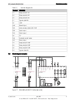
Connected to the safety relay are 16 numbered terminals to which the cables for the various functions are 

connected.

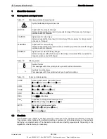
DANGER

Risk of death by electric shock!
Depending on external wiring, dangerous voltages may be present at the switching outputs.

During all work at the electrical system or electronics, make certain that each voltage supply has been 

interrupted and protected against being restarted.

WARNING

Improper electrical connection may result in serious injury!

Only allow competent persons to perform the electrical connection.

Make certain that supply and signal lines are laid separately from power lines.

Use appropriate spark extinction for contactors in the cabinet.

Observe the installation notices and operating instructions of the products that are to be connected via 

the safety relay (drive motors, brakes, etc.).

WARNING

Selecting the wrong functions may result in serious accidents!

Always connect safety sensors to an external safety relay and activate the restart interlock.

For access guarding, make certain that the restart interlock cannot be unlocked from within the danger 

zone but that the danger zone can be viewed from the acknowledgment button (Reset).

Select the functions so that the safety relay is used as intended (see chapter 2.1 „Approved purpose 

and foreseeable improper operation“).

Phone: 800.894.0412 - Fax: 888.723.4773 - Web: www.clrwtr.com - Email: [email protected]

Содержание MSI-SR4B

Страница 1: ...MSI SR4B Safety relays EN 2013 10 50124419 We reserve the right to make technical changes Phone 800 894 0412 Fax 888 723 4773 Web www clrwtr com Email info clrwtr com ...

Страница 2: ...ments 13 7 2 Circuit diagram examples 14 8 Starting up the device 16 8 1 Switching on 16 8 2 Start restart 16 8 2 1 Unlocking start restart interlock 16 9 Testing 17 9 1 Before the initial start up and following modifications 17 9 1 1 Checklist initial start up 17 9 2 To be performed periodically by a competent person 18 9 3 To be performed daily by the operating personnel 19 9 3 1 Check list dail...

Страница 3: ...minor injury if the measures for danger avoid ance are not followed WARNING Signal word for serious injury Indicates dangers that may result in serious or fatal injury if the measures for danger avoidance are not followed DANGER Signal word for life threatening danger Indicates dangers with which serious or fatal injury is imminent if the measures for danger avoidance are not followed Symbol for t...

Страница 4: ...HA 1910 Subpart 0 Safety regulations Accident prevention regulations and safety rules Industrial safety regulation and employment protection act Product Safety Act 2 1 Approved purpose and foreseeable improper operation 2 1 1 Proper use For safety related information you may also contact the local authorities e g industrial inspec torate employer s liability insurance association labor inspectorat...

Страница 5: ...y must not be altered When manipulating the safety relay the pro tective function is no longer guaranteed Manipulating the safety relay also voids all warranty claims against the manufacturer of the safety relay The safety relay must be tested regularly by a competent person see chapter 9 Testing The safety relay must be exchanged after a maximum of 20 years Repairs or the exchange of parts subjec...

Страница 6: ...mpetent persons 2 4 Disclaimer Leuze electronic GmbH Co KG is not liable in the following cases Safety relay is not used as intended Safety notices are not adhered to Reasonably foreseeable misuse is not taken into account Mounting and electrical connection are not properly performed Proper function is not tested see chapter 9 Testing Changes e g constructional are made to the safety relay Phone 8...

Страница 7: ...the cabinet and is wired via the 16 terminals All connection terminals are pluggable The individual terminal blocks are mechanically coded to prevent swapping or skewed plug in The safety relays are available with screw terminals or spring cage terminals Figure 3 3 Internal circuit diagram MSI SR4B Figure 3 1 MSI SR4B with screw terminals Figure 3 2 MSI SR4B with spring cage terminals N O N O 13 2...

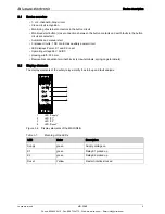
Страница 8: ... Power K1 and K2 reset Operating voltage 24 V AC DC Housing width 22 5 mm Removable connection terminal blocks screw terminals spring cage terminals 3 2 Display elements The display elements of the safety relay simplify the start up and fault analysis 1 LED Supply 2 LED K1 3 LED K2 4 LED Reset Figure 3 4 Display elements of the MSI SR4B Table 3 1 Meaning of the LEDs 1 2 3 4 LED Color Description S...

Страница 9: ...ed signal sequence when using two forced position switches the direction depen dent actuation of the contacts e g of a safety guard is monitored For automatic start bridge S34 S35 reaching or stepping behind must not be possible Signal sequence monitoring The function expects the first signal at S22 and the second signal at S12 The time offset is arbitrary If due to e g misalignment of a contact a...

Страница 10: ... 1 2009 Single channel protective door monitoring up to category 2 EN ISO 13849 1 2009 Two channel protective door monitoring up to category 4 EN ISO 13849 1 2009 Sequential circuit for safety sensor semiconductor outputs two channel self testing Figure 5 1 Guarding a robot area with S400 safety hinge switch and MSI SR4B safety relay Phone 800 894 0412 Fax 888 723 4773 Web www clrwtr com Email inf...

Страница 11: ...6 2 Snap the safety relay onto the DIN rail The safety relay can be connected to the safety sensors WARNING Improper mounting may result in serious injury The protective function of the safety relay is only ensured if appropriately and professionally mounted for the respective intended area of application Only allow competent persons to install the safety relay Observe the relevant standards regul...

Страница 12: ... death by electric shock Depending on external wiring dangerous voltages may be present at the switching outputs During all work at the electrical system or electronics make certain that each voltage supply has been interrupted and protected against being restarted WARNING Improper electrical connection may result in serious injury Only allow competent persons to perform the electrical connection ...

Страница 13: ...t A2 0V S34 Automatic restart output S31 Sensor input 14 Relay contact 1 OUT 24 Relay contact 2 OUT 34 Relay contact 3 OUT 42 Signal contact IN MLCx10R VIN1 VIN1 RNG OSSD2 MLCx00T OSSD1 VIN2 FE Shield FE Shield VIN2 Var B Var A 4 BN BK WH A1 1 2 3 4 A2 1 2 3 BN BK W1 W2 5 W2 GY BU W1 5 GY BU K3 K4 K4 K3 0V PE 24V PE 24V 0V n c 14 24 42 13 23 41 A1 A2 K3 1 2 1 2 L L L L S1 K3 K4 24V 0V MSI SR4B A1 ...

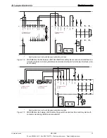
Страница 14: ...RS4 4 FP 1 n c n c OSSD2 OSSD1 X1 X2 reserved n c n c RS232 422 RxD RxD TxD TxD 8 1 15 9 1 5 6 9 13 6 7 8 A1 X2 1 X1 2 X1 1 3 12 11 10 9 OG WH BK W1 8 WH 7 4 5 3 W1 6 5 SH BK 4 14 15 2 9 1 2 RD BU Var A K3 K4 Var B K4 K3 0V PE 24V PE 24V 0V 0V 1 Shield Alarm 2 14 24 42 13 23 41 1 2 1 2 L L K3 K4 24V 0V MSI SR4B A1 A2 A2 S22 S12 S31 S33 S34 S35 2 AOPD 1 AOPD 33 34 2 AOPD IV 0 RES 0 RES I A1 A2 K3 L...

Страница 15: ...s interruptions triggering of the protective function failure of the voltage supply see chapter 8 2 1 Unlocking start restart interlock 8 2 1 Unlocking start restart interlock The red and yellow LEDs illuminate as long as the restart is disabled Make certain that the active protective field is clear If the active protective field is not clear select a different procedure Make certain that there ar...

Страница 16: ...nsibility of the operating company Check whether the safety relay was correctly selected acc to the locally applicable regulations and directives Check whether the safety relay is operated acc to the specified environmental conditions see chapter 13 Technical data Make certain that the safety relay is protected against overcurrent Perform a visual inspection for damage and test the electrical func...

Страница 17: ...ty distance protective field to the next point of operation main tained Are all points of operation of the machine accessible only through the protective field Are all additional protective devices e g safety guards correctly mounted and pro tected against tampering Is the command device for triggering the start restart interlock of the safety relay or the machine mounted in accordance with specif...

Страница 18: ...rsonnel or instructed person Table 9 2 Check list daily or at change of shift WARNING Unpredictable machine behavior during the test may result in serious injury Make certain that there are no people in the danger zone WARNING Faults during the daily inspection may result in serious injury If you answer one of the items on the check list see table 9 2 with no the machine must no longer be operated...

Страница 19: ...Maintenance Leuze electronic MSI SR4B 20 10 Maintenance The safety relay is maintenance free Phone 800 894 0412 Fax 888 723 4773 Web www clrwtr com Email info clrwtr com ...

Страница 20: ...g Leuze electronic MSI SR4B 21 11 Disposing For disposal observe the applicable national regulations regarding electronic components Phone 800 894 0412 Fax 888 723 4773 Web www clrwtr com Email info clrwtr com ...

Страница 21: ...e 49 0 7021 573 0 Service hotline 49 0 8141 5350 111 Monday to Thursday 8 00 a m to 5 00 p m UTC 1 Friday 8 00 a m to 4 00 p m UTC 1 Return address for repairs Service Center Leuze electronic GmbH Co KG In der Braike 1 D 73277 Owen Germany Phone 800 894 0412 Fax 888 723 4773 Web www clrwtr com Email info clrwtr com ...

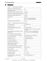
Страница 22: ...cts 1 normal closed contact Ag alloy Switching capacity of the contacts acc to EN IEC 60947 5 1 AC 15 230 V 5 A 1 6x10⁵ switching cycles DC 13 24 V 3 A 1 3x10⁵ switching cycles Max continuous current per current path 3 A Ext contact fuse protection per current path 5 A quick action or 3 15 A delay action Max switching frequency 3600 switching cycles h Mechanical life time 10 million switching cycl...

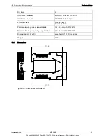
Страница 23: ...nce rejection EN 61496 1 2005 type 4 Protection class Housing IP 40 Terminals IP 20 Permissible wire gauge screw terminals 0 2 2 5 mm2 AWG 24 12 Permissible wire gauge spring cage terminals 0 2 1 5 mm2 AWG 24 16 Dimensions H x W x D see chapter 13 1 Dimensions Weight 170 g 99 0 114 1 111 5 Phone 800 894 0412 Fax 888 723 4773 Web www clrwtr com Email info clrwtr com ...

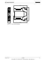
Страница 24: ...Technical data Leuze electronic MSI SR4B 25 Figure 13 2 Dimensions MSI SR4B 02 22 5 111 114 1 111 5 Phone 800 894 0412 Fax 888 723 4773 Web www clrwtr com Email info clrwtr com ...

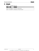
Страница 25: ...er guide Table 14 1 MSI SR4B safety relays Part no Article Description 547950 MSI SR4B 01 Safety relay screw terminals 547951 MSI SR4B 02 Safety relay spring cage terminals Phone 800 894 0412 Fax 888 723 4773 Web www clrwtr com Email info clrwtr com ...

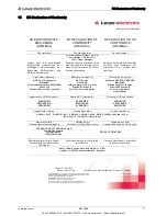
Страница 26: ...ion of product Description de produit NOT HALT Schaltgerät MSI SR4B Sicherheitsbauteil nach 2006 42 EG Anhang IV Seriennummer siehe Typschild E STOP relay MSI SR4B safety component in acc with 2006 42 EC annex IV Serial no see name plates Module d ARRÊT D URGENCE MSI SR4B Èlément de sécurité selon 2006 42 CE annexe IV N série voir plaques signalétiques Angewandte EG Richtlinie n Applied EC Directi...

Отзывы: