background image

Configuration and diagnostics software - Sensor Studio

Leuze electronic

BCL 95

32

6.5.5

Reference code tab

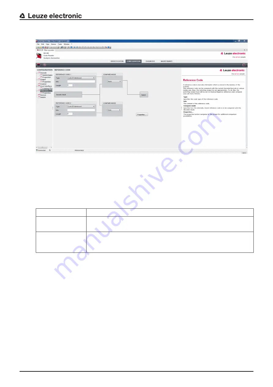
Fig. 6.11: 

Reference code tab

A reference code is bar code information which is stored in the memory of the scanner.

The reference code can be compared with the current decoded bar code in various modes and, thus, the
switching output be set appropriately. For this purpose, the switching output must be set to 

Reference

Code Compare

 (

Positive Reference Code Compare

 or 

Negative Reference Code Compare

) in the

switching output (switch)

 menu.

One possibility to save the reference code is to manually enter the value in this menu. For other possibili-
ties offered by the reference code teach-in, see chapter 8 "Online commands".

Type

Selection of code type.

Contents

(Info)

Contents of the reference code.

Comparison mode

Select here how the internally stored reference code is to be compared with the
decoded result.

For additional comparison possibilities, select the 

Properties

 dialog box.

Содержание BCL 95

Страница 1: ...O r i g i n a l o p e r a t i n g i n s t r u c t i o n s EN 2018 08 50140970 We reserve the right to make technical changes BCL 95 Bar code reader ...

Страница 2: ... 2018 Leuze electronic GmbH Co KG In der Braike 1 D 73277 Owen Germany Phone 49 7021 573 0 Fax 49 7021 573 199 http www leuze com info leuze com Leuze electronic BCL 95 2 ...

Страница 3: ... 1 Operating voltage 17 5 2 Housing ground 17 5 3 Pin assignment 18 5 4 Switching input 18 5 5 Switching output 19 5 6 Cable lengths and shielding 20 5 7 PC or terminal connection 20 6 Configuration and diagnostics software Sensor Studio 21 6 1 System requirements 21 6 2 Installing Sensor Studio 22 6 2 1 Downloading configuration software 22 6 2 2 Installing the Sensor Studio FDT frame 22 6 2 3 In...

Страница 4: ...0 8 Online commands 41 8 1 Overview of commands and parameters 41 8 2 General online commands 42 8 3 Online commands for system control 45 8 4 Online commands for the parameter set operations 46 9 Care maintenance and disposal 50 10 Diagnostics and troubleshooting 51 11 Service and support 52 11 1 What to do should servicing be required 52 12 Technical data 53 12 1 General specifications 53 12 2 R...

Страница 5: ...are not followed CAUTION Signal word for minor injuries Indicates dangers that may result in minor injury if the measures for danger avoidance are not followed WARNING Signal word for serious injury Indicates dangers that may result in severe or fatal injury if the measures for danger avoidance are not followed Tab 1 2 Other symbols Symbol for tips Text passages with this symbol provide you with f...

Страница 6: ...etic compatibility EN European standard FDT Field Device Tool Software frame for management of device managers DTM FE Functional earth GUI Graphical user interface HID Human Interface De vice Device class for input devices with which users directly interact NC Not Connected This pin is not contacted at the device PLC Programmable Logic Control corresponds to Programmable Logic Controller PLC SW_IN...

Страница 7: ...o KG is not liable for damages caused by improper use Ä Read these operating instructions before commissioning the device Knowledge of the oper ating instructions is an element of proper use NOTICE Comply with conditions and regulations Ä Observe the locally applicable legal regulations and the rules of the employer s liability insur ance association CAUTION UL applications For UL applications use...

Страница 8: ...training knowledge and experience as well as their familiarity with relevant standards and regulations certified electricians are able to perform work on electrical systems and independently de tect possible dangers In Germany certified electricians must fulfill the requirements of accident prevention regulations DGUV German Social Accident Insurance provision 3 e g electrician foreman In other co...

Страница 9: ...legal and local regulations regarding protection from laser beams in its latest version Ä The device must not be tampered with and must not be changed in any way There are no user serviceable parts inside the device Ä Repairs must only be performed by Leuze electronic GmbH Co KG WARNING LASER RADIATION LASER CLASS 2 Ä If the scanner motor fails during the emission of laser radiation the limit valu...

Страница 10: ...or the place of use When using the device in the US use the stick on label with the Complies with 21 CFR 1040 10 notice Ä Affix the laser information and warning signs near the device if no signs are attached to the device e g because the device is too small or if the attached laser information and warning signs are concealed due to the installation position Affix the laser information and warning...

Страница 11: ...Safety Leuze electronic BCL 95 11 Fig 2 2 Laser warning and notice signs supplied stick on labels ...

Страница 12: ...eristics see chapter 12 Technical data 3 1 2 Stand alone operation The bar code reader is operated as a stand alone single device The electrical connection of the operat ing voltage the interface and the switching input is made via a 6 wire cable with open cable ends or via an 8 pin M12 connector 3 2 Performance characteristics Laser scanner with integrated decoder lateral or frontal beam exit Hig...

Страница 13: ...aser warning sign 6 Connection cable 6 wire with open cable end Pigtail with M12 connector 8 pin 7 M2 5 mounting threads on the device side 8 M3 mounting threads on the rear of the device Fig 3 1 Device construction of the BCL 95 3 4 Connection technology 6 wire connection cable with open cable end or pigtail with 8 pin M12 connection plug Voltage supply 1 switching input 1 switching output Proces...

Страница 14: ...d sta tus LED Display Description Status LED PWR Green flashing Initialization phase Green continuous light Operational readiness Red flashing 200 ms Warning Red continuous light Error no function Orange flashing 200 ms Service operation Decode LED GOOD READ Green 200 ms on Reading successful Red 200 ms off No reading result Orange continuous light Reading gate active ...

Страница 15: ...ight influence no direct sunlight In order to select the right mounting location several factors must be considered Size orientation and position tolerance of the bar codes on the objects to be scanned The reading field of the bar code reader in relation to the bar code module width The resulting minimum and maximum reading distance from the respective reading field with the re spective module wid...

Страница 16: ...Mounting Leuze electronic BCL 95 16 α β γ α Azimuth angle β Angle of inclination γ Angle of rotation Recommended angle of rotation γ 10 Fig 4 1 Definition of the reading angles ...

Страница 17: ...e cables and lines so that they are protected against external damages Ä For further information see EN ISO 13849 2 Table D 4 The electrical connection is established via the connection cable see chapter 5 3 Pin assignment 6 wire connection cable with open cable end Pigtail with M12 connector 8 pin The bar code reader is provided with the following interfaces Voltage supply 1 switching input 1 swi...

Страница 18: ...2 RS 232 connection cable Core color Signal Description IN OUT Red 5 VDC Voltage supply 5 VDC IN Orange SW IN Switching input IN Violet GND Voltage supply 0 VDC Ground IN Black SW OUT Switching output OUT White RS 232 RxD Serial interface IN Green RS 232 TxD Serial interface OUT Drain wire FE Shield Functional earth shield 5 4 Switching input By means of the SW IN switching input connection you ca...

Страница 19: ...gger a read process by applying a volt age of 5 V DC pin 1 red at SW IN pin 2 orange 5 V DC SW_IN GND GND 4 75 5 5 V DC 1 2 3 1 Pin 1 red 2 Pin 2 orange 3 Pin 3 violet Connection version PNP inverted setting high active input resistance 36 kΩ Fig 5 3 Switching input for connection variant PNP inverted setting 5 5 Switching output The NPN switching output connection between SW OUT pin 4 black and G...

Страница 20: ...e the maximum cable lengths Connection Interface Max cable length Shielding BCL 95 RS 232 3 m Required Switching input Switching output 3 m Not necessary NOTICE Ä Make certain that the cables of the RS 232 interface are shielded should a cable extension be necessary 5 7 PC or terminal connection Via the RS 232 service interface you can configure the bar code reader by means of a PC or a terminal p...

Страница 21: ... The individual DTM configurations of a project can be called up via the frame application of the Field Device Tool FDT Communication DTM for bar code readers LeCommInterface Device DTM for the BCL 95 bar code reader Procedure for the installation of the software and hardware Ä Install the Sensor Studio configuration software on the PC Ä Install the communication and device DTM Communication and d...

Страница 22: ...OTICE If FDT frame software is already installed on your PC you do not need the Sensor Studio instal lation You can install the communication DTM and the device DTM in the existing FDT frame Com munication DTM and device DTM are included in the LeAnalysisCollectionSetup installation package Ä Start the PC Ä Download the configuration software from the Internet to the PC see chapter 6 2 1 Downloadi...

Страница 23: ... the Project Wizard is displayed Ä Select the Device selection without communication connection offline configuration mode and click on Next ð The Project Wizard displays the device selection list of the configurable devices Fig 6 1 Device selection for the BCL 95 Ä Select BCL 95 in the device selection and click on Next ð The device manager DTM of the connected bar code reader starts with the off...

Страница 24: ...ram via File Exit Ä Save the configuration settings as a configuration project on the PC 6 5 Configuration parameters In this chapter you will find information and explanations on the configuration parameters of the device manager DTM for the bar code reader NOTICE This chapter does not include a complete description of the Sensor Studio configuration soft ware Complete information on the FDT fram...

Страница 25: ...re not decoded Note We recommend enabling only the code types which are to actually be read with the corresponding element numbers Number of digits Element number In the field Element number up to 3 element entries may be entered A range of permissible elements is indicated by a dash e g 4 40 elements To select a range set the check mark beneath Interval mode Up to 3 fixed element numbers with com...

Страница 26: ... In the Symbology Properties window to the right of the respective code after Element number the code specific settings such as the check digit can be selected Alternatively you can select the property settings directly via the nav igation tree with the Symbologies button The properties can be individually set for each code type Fig 6 4 Standard settings of the Properties dialog box Symbology Prop...

Страница 27: ...f empty space to the left and right By default the scanner checks a quiet zone that is 7x greater than the module Reading reliability Equal scans Specifies how often a code must be decoded before the result is valid and output No time correlation between two identical scans If this parameter is set a gap between two identical labels is ignored and they are treated as a single label No position cor...

Страница 28: ...s sent in a separate message before the read result Label header The label header is set directly before the code data Label footer The label footer is appended directly to the code data Message mode Selects whether the bar codes read are sent in con catenation or separately as individual strings NOTICE The structure of this message string is depicted symbolically in the preview window ...

Страница 29: ...ding No read string This character is set for each unrecognized bar code Multiple characters string may be entered here Up to 20 characters are possible Properties Output Properties Set the desired formatting modes and formatting characters as necessary Fig 6 7 Standard settings of the Properties dialog box ...

Страница 30: ...u tostart after decode Is normally used for test purposes Deactivation Switching input 1 Function See menu switching input Immediately after the complete de coding result is available If the setting is activated the read result is output immediately after the bar code is decoded If the setting is deactivated the read result is sent only after the trig ger signal is returned end of reading gate Com...

Страница 31: ...ader standard pro cedure The desired acknowledgment settings are also to be set in this selection window Properties dialog box Framing Protocol Fig 6 10 Standard settings of the Properties dialog box Framing Protocol Here you can change the address settings and the protocol for sending and receiving NOTICE To be able to continue to communicate with a device following a parameter transfer you may n...

Страница 32: ...g output must be set to Reference Code Compare Positive Reference Code Compare or Negative Reference Code Compare in the switching output switch menu One possibility to save the reference code is to manually enter the value in this menu For other possibili ties offered by the reference code teach in see chapter 8 Online commands Type Selection of code type Contents Info Contents of the reference c...

Страница 33: ...Configuration and diagnostics software Sensor Studio Leuze electronic BCL 95 33 Fig 6 12 Standard settings of the Properties dialog box ...

Страница 34: ...up delay time The trigger signal is passed on delayed by the specified time period Pulse duration If the value is higher than 0 duration of the activation regardless of how long the trigger signal has been applied Switch off delay Delay off time After the end of the trigger signal the pulse is extended internally by this time period Function Control Event that is started when the switching input i...

Страница 35: ...ut here Multiple events can also be simultaneously activated Deactivation Shown here is the event which results in the switching output being reset if the set pulse duration has not yet expired Multiple events can also be simultaneously activated Inverted Here the input level can be inverted Pulse duration Duration of the switching output pulse Pulse delay Pulse delay time Length of time before th...

Страница 36: ...General online com mands command V You can use this command to check whether the communication between PC and scanner is functional If you do not receive an acknowledgment please check the interface connections or the protocol Device Identification Query of the serial number as well as the hardware and software versions Reset Carries out a software reset The device is restarted and reinitialized l...

Страница 37: ...load tool Click the Browse button A dialog box for selecting the firmware file mot opens Ä Once the firmware file is loaded in the Firmware Reload tool click on the Start Reload button to load the new firmware into the device The device is connected via the serial interface specified under Port The Firmware Reload tool checks whether the new firmware is compatible with the device If the new firmwa...

Страница 38: ...face Proper function of the interface can most easily be tested in service operation using the RS 232 interface with the Sensor Studio configuration software 7 2 3 Online commands Using the online commands important device functions can be checked e g reading activation see chap ter 8 Online commands You can use online commands to directly send control and configuration commands to the device You ...

Страница 39: ...gs The configuration settings are stored in the memory of the bar code reader in parameter sets The various parameter sets are explained to understand what is happening during configuration parameter setting see chapter 7 4 2 Parameter sets The setting of code type and code length is usually accomplished by using the Sensor Studio configu ration software see chapter 6 Configuration and diagnostics...

Страница 40: ...s loaded into the memory of the bar code reader The first time the device is commissioned after delivery With the Sensor Studio configuration software via the Factory Default button in the DIAGNOSIS menu After the online command PC20 see chapter 8 4 Online commands for the parameter set operations If the checksums of the current parameter set are invalid Current parameter set In this parameter set...

Страница 41: ...cs you can send online commands to the device via the Sensor Studio configura tion software DIAGNOSIS Terminal 8 1 Overview of commands and parameters NOTICE The following chapters describe the input of online commands via a terminal program To input online commands via the Sensor Studio configuration software see chapter 6 Configuration and diagnostics software Sensor Studio Syntax Online command...

Страница 42: ...ns or the protocol Software reset Command H Description Carries out a software reset The device is restarted and reinitialized leaving it in the same state as when the operating voltage is switched on Parameter None Acknowledgment S start signal autoConfig Command CA Description Activates or deactivates the autoConfig function Certain label reading parame ters are programmed automatically in the s...

Страница 43: ...input via the serial interface The data is saved in the parame ter set according to your input under reference code 1 or 2 and stored in the working buffer for direct further processing Parameter RSyvxxzzzzzzzz y v x and z are placeholders variables for the actual input y Def reference code no 1 code 1 2 code 2 v Storage location for reference code 0 RAM EEPROM 3 RAM only xx Def code type see comm...

Страница 44: ...al input y Def reference code no 1 code 1 2 code 2 v Storage location for reference code 0 RAM EEPROM 3 RAM only xx Def code type see command CA z Def code information 1 30 characters NOTICE With this function only code types are recognized that are identified using the autoConfig func tion or which were set in the set up Ä After each reading via an RTy command explicitly switch off the function a...

Страница 45: ... the scanner is set to terminate the decoding after 100 success fully decoded labels and output the status information Subsequently the read process is reactivated automatically As status the output returns the following values Scans which contain the valid label information on the basis of 100 scans Decoding result These values can be used to determine the decoding quality If the reading quality ...

Страница 46: ...et data stored in the EEPROM non volatile 1 Reserved 2 Standard parameter set not changeable 3 Operating values data in the RAM will be lost after reset Status Mode of parameter processing 0 Does not perform a reset following the write operation no other parameters follow 1 Does not perform a reset following the write operation other parameters follow 2 Subsequently performs a reset no additional ...

Страница 47: ...h 6 Invalid message data 7 Invalid start address 8 Invalid parameter set 9 Invalid parameter set type Copying parameter set Command PC Description The command copies complete parameter sets Parameter 03 Copy parameters from the EEPROM into the RAM and initialize all associated functions 20 Copy standard parameters from the FLASH into the EEPROM and RAM and initialize all relevant functions 30 Copy...

Страница 48: ...id data length 6 Invalid message data 7 Invalid start address 8 Invalid parameter set 9 Invalid parameter type Example PR00102004 Beginning with address 102 four 004 bytes are read out and transferred Acknowledge parameter message Command PS Description The command acknowledges the received message and delivers an acknowl edgment status which indicates whether the message was valid or invalid Para...

Страница 49: ...pe in the EEPROM The transmission can optionally occur with a block check test of the message data Parameter BCC type PS type Status Start address Para0L Para0H Para122L BCC Acknowledgment PSx x Status 0 Valid transfer 1 Invalid message 2 Invalid message length 3 Invalid block check type 4 Invalid block check checksum 5 Invalid data length 6 Invalid message data 7 Invalid start address 8 Invalid p...

Страница 50: ...free cloth Tips and hard objects damage the lens Maintenance Usually the bar code reader does not require any maintenance by the operator Repairs to the device must only be carried out by the manufacturer Ä For repairs contact your responsible Leuze electronic subsidiary or Leuze electronic customer service see chapter 11 Service and support Firmware Reload You can load a different firmware into t...

Страница 51: ...uery diagnostic data in the device and carry out the resulting measures or reset Red continuous light Serious error No function possible Internal device error Contact Leuze electronic customer service see chapter 11 Service and support Orange flashing Service operation is active Reset service operation e g by resetting or interrupting the supply voltage Error Possible error cause Measures No commu...

Страница 52: ...Service center Leuze electronic GmbH Co KG In der Braike 1 D 73277 Owen Germany 11 1 What to do should servicing be required NOTICE Please use this chapter as a master copy should servicing be required Ä Enter the contact information and fax this form together with your service order to the fax number given below Customer data please complete Device type Serial number Firmware Status of LEDs Error...

Страница 53: ... Tab 12 2 Code specifications Code types 2 5 Interleaved Code 39 Code 128 EAN 128 Pharmacode Code 93 Codabar EAN Addendum Code 32 EAN 8 EAN 13 UPC A UPC E Module width distance dependent 0 15 mm 0 5 mm 6 mil 20 mil Print quality ANSI X3 123 DIN EN 1635 class A B Angle of rotation 10 Tab 12 3 Interfaces Process interface RS 232 Baud rate 4800 57600 baud Data formats Data bits 7 8 Parity none even o...

Страница 54: ... IP 54 Connection type Connection cable 2 m long 6 wire with open cable end Pigtail with M12 connector 8 pin Weight Approx 210 g Dimensions see chapter 12 3 Dimensioned drawings Fastening 2 M2 5 mounting threads 4 mm deep on the side of the device 2 M3 mounting threads 6 mm deep on the rear of the device Housing Diecast zinc Optics cover Glass Tab 12 6 Environmental data Ambient temperature Operat...

Страница 55: ...contrast etc and may thus deviate from the read ing fields specified here The origin of the read distance always refers to the front edge of the housing of the beam exit 186 166 41 40 40 170 BCL95 M2 R2 BCL95 M0 R2 150 25 40 40 1 2 1 2 all dimensions in mm The reading fields are specified for Code128 four width code 1 M 0 165 mm 0 2 mm 6 5 mil 8 mil 2 M 0 2 mm 0 5 mm 8 mil 20 mil Fig 12 1 BCL 95 r...

Страница 56: ... Leuze electronic BCL 95 56 12 3 Dimensioned drawings BCL 95 dimensioned drawings all dimensions in mm A Laser beam B1 Indicator diode decode LED B2 Indicator diode status LED Fig 12 2 BCL 95 M2 R2 frontal beam exit ...

Страница 57: ...Technical data Leuze electronic BCL 95 57 all dimensions in mm A Laser beam B1 Indicator diode decode LED B2 Indicator diode status LED Fig 12 3 BCL 95 M0 R2 lateral beam exit ...

Страница 58: ...rontal Connection cable 6 wire 2 m 13 2 Accessories Tab 13 2 Accessories connection cables Part no Part designation Description 50135121 KD U M12 8A P1 020 Connection 1 connector M12 axial female A coded 8 pin Connection 2 open cable end Shielded no Cable length 2000 mm Material sheathing PUR 50135122 KD U M12 8A P1 050 Connection 1 connector M12 axial female A coded 8 pin Connection 2 open cable ...

Страница 59: ...f Conformity Leuze electronic BCL 95 59 14 EC Declaration of Conformity The bar code readers of the BCL 95 series have been developed and manufactured in accordance with the applicable European standards and directives ...

Страница 60: ... Bar code samples Module 0 3 Fig 15 1 Code type 01 Interleaved 2 of 5 Module 0 3 Fig 15 2 Code type 02 Code 39 Module 0 3 Fig 15 3 Code type 11 Codabar Module 0 3 Fig 15 4 Code 128 Module 0 3 Fig 15 5 Code type 08 EAN 128 SC 2 Fig 15 6 Code type 06 UPC A ...

Страница 61: ...Appendix Leuze electronic BCL 95 61 SC 3 Fig 15 7 Code type 07 EAN 8 ...

Отзывы: