


LEROY-SOMER
4946 - 2013.07 / a
POWERDRIVE MD2CS
32
en
InstallatIon and maIntenance
Chassis-mounted variable speed drive
PaRameteR-settInG InteRFace and oPtIons
5.1 - Parameter setting
5.1.1 - MDX-Powerscreen
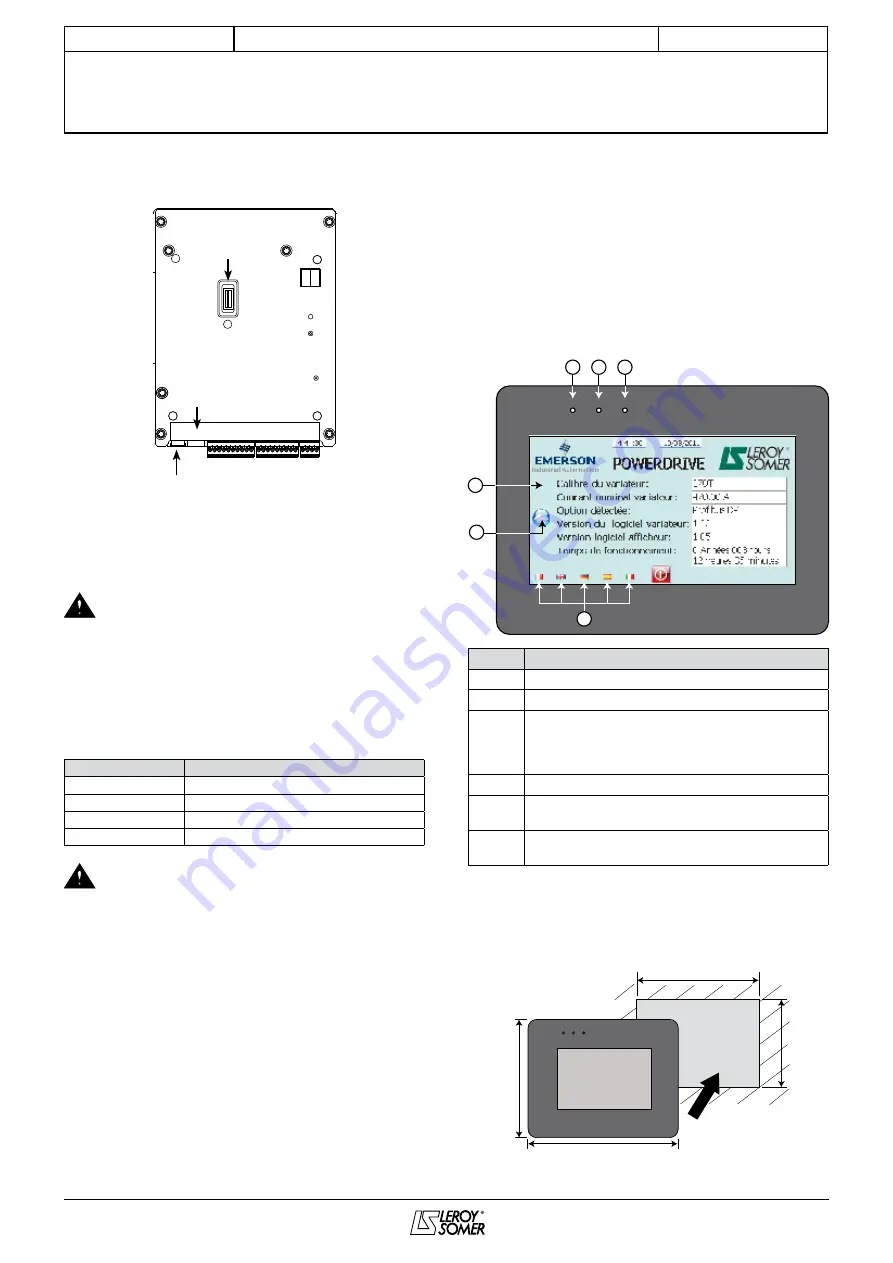
• General
the PoWeRscReen interface is a touch screen which can
be used to access various menus to setup and supervise the
drive.
after the loading phase following the power-up of the drive,
the parameter-setting interface displays the screen below in
french. select language using the "F" buttons below
COM
CPU
PWR
F
C
D
E
A
B
Ref.
Function
a
4.3" touch screen
B
touch-sensitive button to access the main menu
c
"com" led, indicates the state of the communication
with the drive.
off: no communication
Flashing: communicating
d
"cPU" led, indicates the status of the interface cPU
e
"PWR" led, indicates the state of the interface power
supply
F
touch-sensitive buttons for language selection (can take
a few minutes to load)
• Installation
The interface is flush-mounted in the front of a cabinet (IP65/
NEMA 4 mounting). It is fixed by 4 screws (tightening 2 Nm).
Cut-out drawing
93 mm
102 mm
119 mm
128 mm
5 - PARAMETER-SETTING INTERFACE AND OPTIONS
• Connection to the drive
Px1
Px2
Px3
P1 P2
1
1
1
connector for optional
fieldbus and/or
speed feeback
connector for mdX-
KeYPad or mdX-
Powerscreen display
UsB connector for
mdX-soFt
◦ P1 connector
this connector is a slave type B UsB socket, and is used to
communicate via Pc using the mdX-soFt software.
In conformity with standard EN 60950, the USB link
can only be used via a device that provides
isolation of 4 kV (MDX-USB isolator option).
◦ P2 terminal block
this is a standard Rs485/Rs422 terminal block which
is used to connect a parameter-setting interface or to
communicate via modbus RtU.
Terminals
Description
1
0V
2
Rx\, tx\
3
Rx, tx
4
24V
Check that control circuits are powered down
before disconnecting the programming interface
from the P2 connector.


