background image

Commissioning

DYNEO

®

Synchronous motors with permanent magnets-drive

2

4474 en - 2011.04 / e

LEROY-SOMER

NOTE

LEROY-SOMER  reserves  the  right  to  modify  the  characteristics  of  its  products  at  any  time  in  order  to  incorporate 

the latest technological developments. The information contained in this document may therefore be changed without 

notice.


CAUTION

For the user’s own safety, the variable speed drive must be connected to an approved earth (  terminal).

If accidentally starting the installation is likely to cause a risk to personnel or the machines being driven, it is essential to 

comply with the power connection diagrams recommended in this manual.

The variable speed drive is fitted with safety devices which, in the event of a problem, control stopping and thus stop 

the motor. The motor itself can become jammed for mechanical reasons. Voltage fluctuations, and in particular power 

cuts, may also cause the motor to stop. The removal of the causes of the shutdown can lead to restarting, which may 

be dangerous for certain machines or installations.

In such cases, it is essential that the user takes appropriate precautions against the motor restarting after an unscheduled 

stop.

The variable speed drive is designed to be able to supply a motor and the driven machine above its rated speed.

If the motor or the machine are not mechanically designed to withstand such speeds, the user may be exposed to 

serious danger resulting from their mechanical deterioration.

It is important that the user checks that the installation can withstand it before programming a high speed.

The variable speed drive which is the subject of this manual is designed to be integrated in an installation or an electrical 

machine, and can under no circumstances be considered to be a safety device. It is therefore the responsibility of the 

machine manufacturer, the designer of the installation or the user to take all necessary precautions to ensure that the 

system complies with current standards, and to provide any devices required to ensure the safety of equipment and 

personnel.

LEROY-SOMER declines all responsibility in the event of the above recommendations not being observed.

..........................................

This manual is not a substitue for the drive installation and commisioning manuals.

Содержание DYNEO

Страница 1: ...DYNEO Synchronous motors with permanent magnets drive Commissioning 4474 en 2011 04 e...

Страница 2: ...machines or installations In such cases it is essential that the user takes appropriate precautions against the motor restarting after an unscheduled stop The variable speed drive is designed to be ab...

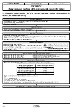
Страница 3: ...LSRPM MAGNETS MOTOR WITH FEEDBACK VIA HALL EFFECT SENSOR CONTROLLED BY A UNIDRIVE SP DRIVE 6 3 COMMISSIONING OF LSRPM MAGNETS MOTOR WITH FEEDBACK VIA ENCODER WITH COMMUTATION CHANNELS CONTROLLED BY A...

Страница 4: ...on each pair U U V V The thermal sensor is connected in the motor terminal box 1 Use shielded cable on each pair U U V V 15 14 13 16 9 3 2 1 4 5 6 7 8 17 12 11 10 _ _ MD ENCODER 3 15V MD Encoder 5V T1...

Страница 5: ...r rated voltage 00 10 Motor rated frequency Enter the motor parameters indicated on the motor nameplate 00 14 Type HALL EFFECT or incremental UVW depending of the sensor used 00 15 Drive encoder lines...

Страница 6: ...t limiting 150 0 41 The SWITCHING FREQUENCY value must be set according to the following table 0 42 Number of poles calculation p 120f n 0 45 Motor thermal constant 89 5 22 Enable high speed ON Enter...

Страница 7: ...ual ref 3655 Setting the control parameters for the motor brake managed by the drive Possible to uncouple the motor YES NO Using the information on the motor nameplate set the following parameters 3 2...

Страница 8: ...and 11 of the drive control terminal block To modify sensor control see parameter 7 15 0 21 2 Connect the shielding 360 round the connector 3 Connect the shielding 360 round the shielding connection...

Страница 9: ...lete the motor stops automatically The procedure can be interrupted at any time by sending a stop command pressing the stop button on the keypad or opening the disable circuit Regardless of the requir...

Страница 10: ...erminal block ADI3 0V terminals and set 00 28 CTP 1 Enter the main parameters 00 06 MOTOR RATED CURRENT A 00 07 MOTOR RATED SPEED rpm 00 08 MOTOR RATED VOLTAGE V 00 10 MOTOR RATED FREQUENCY Hz 05 24 E...

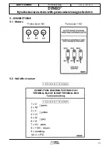
Страница 11: ...04 e LEROY SOMER 5 CONNECTIONS 5 1 Motors U1 L1 V1 L2 W1 L3 5 2 Hall effect sensor Frame size 160 Frame size 160 1 U 2 W 3 V 4 U 5 W 6 V 7 0V white 8 15V brown 9 shielding 10 11 PTC green yellow grey...

Страница 12: ...3 14 15 16 17 Pins 1 to 3 are not connected The cable general shielding is connected to the connector casing 5 4 Forced ventilation Black W V CP2 C P 1 Z U Blue Brown Motor type Capacitors CP1 CP2 LS...

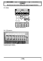
Страница 13: ...474 en 2011 04 e LEROY SOMER 5 5 Brake Power supply Coil 400 VAC 230 VAC 180 VDC 180 VDC Wiring 2 1 Coil Power supply S O8 _ A 15 2 1 depending on power supply and coil depending on power supply and c...

Страница 14: ...Commissioning DYNEO Synchronous motors with permanent magnets drive 14 4474 en 2011 04 e LEROY SOMER...

Страница 15: ...15 Commissioning DYNEO Synchronous motors with permanent magnets drive 4474 en 2011 04 e LEROY SOMER...

Страница 16: ...MOTEURS LEROY SOMER 16015 ANGOUL ME CEDEX FRANCE 338 567 258 RCS ANGOUL ME S A au capital de 62 779 000 www leroy somer com...

Отзывы: